In the previous post, we saw how to use digital inputs to receive signals from the world. However, if we could only perform readings, automations wouldn’t be very useful (at least, they would have much less utility than they do).
Now we are going to learn how to use Arduino’s outputs to perform actions in the world. We’ll start with digital outputs, as they are simpler than analog ones.
What is a Digital Output
We will remember that a digital signal can only vary between two values, which we call -Vcc and +Vcc (for example, 0 and 5V).
A digital output is a device that allows its voltage to be switched to one of these two values through programming. Therefore, we can use them to perform actions with the environment.
In Arduino, generally, the -Vcc and +Vcc voltages correspond to 0V (GND) and 5V. However, some Arduino models operate at 3.3V, such as some Mini, Nano, and boards based on ARM processors like the Arduino Due.
All digital pins on Arduino can act as digital outputs (that’s why they are called I/O, input and output).
It is less known that all analog pins can also be used as digital inputs and outputs.
The exact number of digital outputs depends on the board model we are using, as we saw in the post What is Arduino? Which model to buy?.
In summary,
- Arduino Uno and Nano have 22 pins that we can use as digital outputs
- Arduino Mini has 20 digital outputs
- Arduino Mega has up to 70 digital outputs
These are more than respectable figures, superior to most industrial-type automations.
Maximum Current of a Digital Output
In general, the digital outputs of automations are not designed to provide power, but to interact with electronics or other automations.
The maximum current a pin can provide is 40 mA, although the recommended value is 20mA. Additionally, there are further power restrictions, such as:
- The total sum of all outputs must be less than 300 mA
- Furthermore, they cannot exceed 150 mA per port.
This power is enough to light an LED, a small 9g servo motor, or power some sensors, but it is not enough to power larger loads.
If we want to drive a larger load, such as a DC motor, a servo, or even a relay, we will have to use an amplification stage (like a BJT, MOSFET transistor).
It is not advisable to push the power limits for prolonged periods as the board could overheat and be damaged. The 20 mA limit per output means that, for a voltage of 5V, the resistance of the device we want to power should not be less than 200 ohms.
As a general rule, unless we know what we are doing, whenever we connect a device to any output we will do it through a resistor of at least 300 ohms.
Digital Output Connection
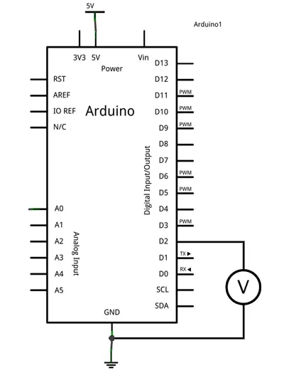
For this tutorial, no setup is necessary. However, we can verify the correct operation of the digital outputs simply by measuring the voltage between the digital output and GND with a multimeter.
Code
The code to turn on an output is similar to what we saw in the tutorial Our First Program in Arduino. In fact, it’s exactly the same, changing the 13 to the pin of the output we want to activate. We’ll remember that pin 13 is a special pin, connected to the built-in LED on the board.
So the following code, which is a modification of the Blink example file, turns a digital output on and off.
const int pin = 2;

void setup() {
  Serial.begin(9600);    //start serial port
  pinMode(pin, OUTPUT);  //define pin as output
}

void loop(){
  digitalWrite(pin, HIGH);   // set the Pin to HIGH
  delay(1000);               // wait one second
  digitalWrite(pin, LOW);    // set the Pin to LOW
  delay(1000);               // wait one second
}
The following code, which we saw in the post about the Arduino serial port, receives a character through the serial port to turn a digital signal on or off from the computer.
Through the serial port we send a character. If we write 0 the output turns off, and if we write 1 it turns on.
const int pin = 2;
int option;

void setup(){
  Serial.begin(9600);
  pinMode(pin, OUTPUT);
}

void loop(){
  //if there is pending information
  if (Serial.available()>0){
    //we read the option
    char option = Serial.read();
    if (option == '0' )  //if the value is 0
    {
         digitalWrite(pin, LOW);  //turn off the pin
    }
    else if (option == '1' )
    {
         digitalWrite(pin, HIGH);  //turn on the pin
    }
    delay(200);
  }
}
That covers the basics of digital outputs in Arduino. In future posts, we will see analog outputs and delve into more advanced aspects of digital outputs.
Download the Code
All the code from this post is available for download on Github. 
