All ESP32 models have two 12-bit SAR (Successive Approximation Register) ADCs (analog-to-digital converter) available, named ADC1 and ADC2.
With a 12-bit resolution, a resolution of 3.3 volts / 4096 units, it is equivalent to 0.8 mV per step. Furthermore, we can programmatically configure the ADC resolution and channel range.
The maximum allowable voltage is 3V3. Although many ESP32 GPIOs are 5V tolerant, the ADC is not. So do not put more than 3.6V on a pin you are using as an analog input, or you will damage the ADC.
The number of pins will depend on the ESP32 model we are using. For example, the ESP32 has 18 pins, organized as follows,
- ADC1 connected to 8 GPIOs (32-39)
- ADC2 connected to 10 GPIOs (0, 2, 4, 12-15 and 25-27)
While an ESP32-S3 has 20 analog pins, organized into,
- ADC1 connected to 10 GPIO (1-10)
- ADC2 connected to 10 GPIO (11-20)
Furthermore, depending on your development board, not all may be available on your board.
When in doubt, consult the full documentation for your model.
Very important, ADC2 is used by the Wi-Fi module, so we cannot use the ADC2 pins when Wi-Fi is enabled. If your project requires Wi-Fi, use only the ADC1 pins.
How to Read the ESP32 Analog Input
Under the Arduino environment, reading an analog input on the ESP32 is exactly the same as we would do on a “conventional” Arduino.
We simply have to use the analogRead(GPIO) function. Which accepts as its only argument the pin number to which the sensor is connected.
For example, this is how we would read the analog value from pin A0 and display it via serial port,
void setup()
{
  Serial.begin(9600);
}

void loop()
{
  int sensorValue = analogRead(A0);
  Serial.println(sensorValue);
  delay(100);
}Otherwise, the operation is similar to analog inputs on Arduino. We can read voltages and resistances or potentiometers.
ADC Attenuation Values
To perform the measurement, the ESP32 compares the voltage we want to measure with a reference value Vref which, by design, is 1.1V.
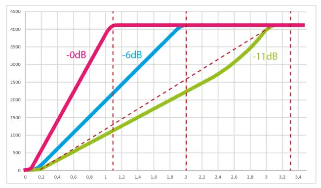
To allow measuring a range of higher voltages, the ESP32 uses a variable gain attenuation circuit. (at -11dB, which is the default value to be able to measure up to 3V3).
The behavior of the ESP32 ADC in its various variants has never been one of its strongest points. See below ‘ADC Accuracy’. Therefore, the manufacturer recommends “optimal” values for the voltages we can measure with the ADC.
ESP32 Attenuation Values
| Attenuation | Preferred Voltage Range |
|---|---|
| ADC_ATTEN_DB_0 | 100 mV ~ 950 mV |
| ADC_ATTEN_DB_2_5 | 100 mV ~ 1250 mV |
| ADC_ATTEN_DB_6 | 150 mV ~ 1750 mV |
| ADC_ATTEN_DB_11 | 150 mV ~ 2450 mV |
ESP32-S3 Attenuation Values
| Attenuation | Preferred Voltage Range |
|---|---|
| ADC_ATTEN_DB_0 | 100 mV ~ 950 mV |
| ADC_ATTEN_DB_2_5 | 100 mV ~ 1250 mV |
| ADC_ATTEN_DB_6 | 150 mV ~ 1750 mV |
| ADC_ATTEN_DB_11 | 150 mV ~ 2450 mV |
ADC Accuracy on the ESP32
Much has been said, and not for the better, about the ESP32 ADC accuracy. The truth is that, traditionally, it is not one of the ESP32’s strongest points.
However, many of the things that have been said are not current today, and apply only to the “normal” ESP32 (not the S2, S3… etc).
The problem with the ESP32 is that, as we said before, the ESP32 compares with an internal Vref value of 1.1V. However, boards come out with different variations that make that 1.1V actually be 1.0 to 1.2V.
On the other hand, at -11dB, the default attenuation value to be able to measure up to 3V3, the attenuation circuit introduces a strongly non-linear behavior.
That is, the response we get is something like this. Quite poor when operating at -11dB.
It is possible to calibrate the ESP32 to improve the ADC behavior. Here is a good repository explaining how to calibrate it easily GitHub - e-tinkers/esp32-adc-calibrate.
However, what is often not mentioned is that from 2019 onwards, ESP32s come factory pre-calibrated and the code was changed to add a software correction. So the behavior is much better.
On the other hand, in the case of the ESP32-S3 things are different. This model includes an internal hardware calibration chip, so the ESP32-S3 response is something like this.
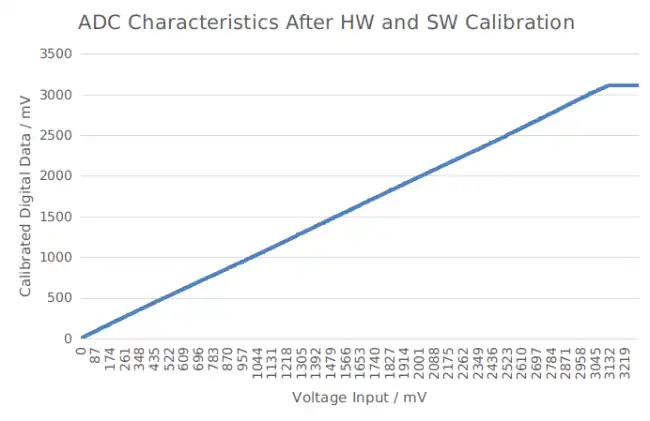
Which is much better than what we had on the old ESP32 (non-versioned).
Finally, even in the old model, the importance of the ESP32’s lack of accuracy must be relativized, depending on what you really need for your project.
That is, if you want the ADC, for example, to read a potentiometer and change the lighting of an LED, or the speed of a motor, it probably works perfectly for you even if you don’t have it calibrated.
If you need a really precise measurement, you probably shouldn’t use the ADC of any processor “raw”, neither the ESP32’s nor a “conventional” Arduino’s.
In that case, you can either perform an ADC calibration, or use a high-precision ADC like the AD1115 we saw in this post 16-bit Analog Input with Arduino and ADC ADS1115
References: