If we want to handle a CPU, the first thing we should do is get to know and familiarize ourselves with its hardware details.
The ESP32 is a much more powerful machine than a “conventional” Arduino or an ESP8266. It offers many more GPIOs, many more features, and has many more components.
In return, it is also considerably more complex. Mainly due to the large number of configuration options and connection possibilities.
So let’s see a summary of the main characteristics of the ESP32. We start by recalling the technical specifications table of the ESP32.
| Feature | ESP32 Series |
|---|---|
| Launch year | 2016 |
| Core | Xtensa® dual-/single core 32-bit LX6 |
| Wi-Fi protocols | 802.11 b/g/n, 2.4 GHz |
| Bluetooth® | Bluetooth v4.2 y BLE |
| Typical frequency | 240 MHz (160 MHz for ESP32-S0WD) |
| SRAM | 520 KB |
| ROM | 448 KB |
| External flash | Up to 16 MB device |
| External RAM | Up to 8 MB device |
| GPIO | 34 |
| ADC | 2x 12-bit |
| DAC | 2x 8-bit |
| Timers | 4x 64-bit, 3x watchdog |
| Temperature sensor | ✖️ |
| SPI | 4 |
| LCD interface | 1 |
| UART | 3 |
| I2C | 2 |
| I2S | 2 |
| LED PWM | 16 |
| Pulse counter | 8 |
| Touch sensor | 10 |
| Hall sensor | 1 |
| Camera interface | 1 |
If you are using an ESP32-S3, you have a similar summary in this entry ESP32-S3 Hardware Details and Pinout
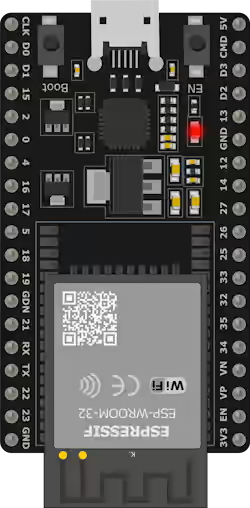
ESP32 Pinout
We start by looking at the pinout diagram of Espressif’s official development board for the ESP32, the ESP32 DevKitC.
Legend and Filtering
(click the buttons to show or hide pins)
- POWER
- GPIO
- ADC
- PWM
- DAC
- RTC
- TOUCH
- UART
- SPI
- I2C
- COMM
- CONTROL
- MISC
- Info
Keep in mind that these are the specifications of this specific board. The one you have on your device will depend on the SoM and the development board you are using.
If you have questions about what a SoC, SoM, and a development board are, check this post What is a SoC and a SoM
In case of any doubt about your board, it is best to consult the official documentation from Espressif and, above all, the information from the device manufacturer.
Here is the link to the official documentation from Espressif about the Esp32 DevKitc 1.
ESP32-DevKitC V4 Getting Started Guide - ESP32 - — ESP-IDF Programming Guide latest documentation
Multiplexing
Pin multiplexing is one of the most important and useful features of the ESP32.
Basically, in the ESP32 we can reassign most functions to act on another pin (without affecting performance).
So, the values we will see are the default values, but generally, you can change them to others as it suits you.
The RTC
The RTC (Real Time Clock) plays a fundamental role during Sleep modes. The RTC consists of the following parts:
- RTC controller (which includes timers and IO peripherals)
- RTC memory (fast and slow)
- Ultra Low Power (ULP) coprocessor
The ESP32 has 8 kB of SRAM in the RTC part, called fast RTC memory. The data stored here is not erased during deep sleep mode.
Additionally, there are another 8kB of SRAM called slow memory, which is used for the ULP processor.
Digital Pins
GPIO Pins
The ESP32 has up to 34 GPIO pins that can be assigned to different functions through programming.
Most of these digital GPIO can be configured with internal pull-up or pull-down resistors.
ESP32 Strapping Pins
There are five Strapping pins.
- GPIO 0 (must be LOW to enter boot mode)
- GPIO 2 (must be floating or LOW during boot)
- GPIO 4
- GPIO 5 (must be HIGH during boot)
- GPIO 12 (must be LOW during boot)
- GPIO 15 (must be HIGH during boot)
These pins are involved in the configuration during boot. So avoid using them in your project.
More information in this post read more
GPIO Input-Only Pins
These pins cannot be used as outputs, but can be used as digital or analog inputs, or for other purposes.
- GPIO 34
- GPIO 35
- GPIO 36
- GPIO 39
Additionally, unlike the other GPIO pins, they lack internal pull-up and pull-down resistors.
ESP32 Interrupt Pins
All GPIO pins can be configured as interrupts.
ESP32 RTC GPIO Pins
Some GPIO are connected to the low-power RTC subsystem and are known as RTC GPIO
- RTC_GPIO0 - GPIO 36
- RTC_GPIO3 - GPIO 39
- RTC_GPIO4 - GPIO 34
- RTC_GPIO5 - GPIO 35
- RTC_GPIO6 - GPIO 25
- RTC_GPIO7 - GPIO 26
- RTC_GPIO8 - GPIO 33
- RTC_GPIO9 - GPIO 32
- RTC_GPIO10 - GPIO 4
- RTC_GPIO11 - GPIO 0
- RTC_GPIO12 - GPIO 2
- RTC_GPIO13 - GPIO 15
- RTC_GPIO14 - GPIO 13
- RTC_GPIO15 - GPIO 12
- RTC_GPIO16 - GPIO 14
- RTC_GPIO17 - GPIO 27
These pins are used to wake the ESP32 from deep low-power mode when the ultra-low-power (ULP) coprocessor is running.
ESP32 Touch Pins
The ESP32 has 10 capacitive touch GPIO pins.
- TOUCH0 - GPIO 4
- TOUCH1 - GPIO 0
- TOUCH2 - GPIO 2
- TOUCH3 - GPIO 15
- TOUCH4 - GPIO 13
- TOUCH5 - GPIO 12
- TOUCH6 - GPIO 14
- TOUCH7 - GPIO 27
- TOUCH8 - GPIO 33
- TOUCH9 - GPIO 32
When a capacitive load (like a human finger) is near the GPIO pin, the ESP32-S3 detects the change in capacitance.
Enable (EN) Pin
Enable (EN) is the pin that controls the 3V3 regulator. It is configured with a pull-up resistor, so it connects to ground to disable the 3.3V regulator. For example, to reset the ESP32.
Analog Pins
ESP32 PWM Pins
The ESP32 board has 16 PWM channels controlled by a PWM controller. The PWM output can be used to control motors and digital LEDs.
ESP32 ADC Pins
The ESP32 integrates two ADCs and supports measurements on 18 channels
- ADC1_CH0 - GPIO 36
- ADC1_CH1 - GPIO 37
- ADC1_CH2 - GPIO 38
- ADC1_CH3 - GPIO 39
- ADC1_CH4 - GPIO 32
- ADC1_CH5 - GPIO 33
- ADC1_CH6 - GPIO 34
- ADC1_CH7 - GPIO 35
- ADC2_CH0 - GPIO 4
- ADC2_CH1 - GPIO 0
- ADC2_CH2 - GPIO 2
- ADC2_CH3 - GPIO 15
- ADC2_CH4 - GPIO 13
- ADC2_CH5 - GPIO 12
- ADC2_CH6 - GPIO 14
- ADC2_CH7 - GPIO 27
- ADC2_CH8 - GPIO 25
- ADC2_CH9 - GPIO 26
The ADCs are 12 bits, so we have 4096 (2^12) discrete levels, which translates to a precision of 0.8mV.
ESP32 DAC Pins
The ESP32 includes two DAC channels to convert digital signals into analog voltages.
- DAC1 - GPIO 25
- DAC2 - GPIO 26
These DACs have an 8-bit resolution, meaning that values ranging from 0 to 255 are converted into an analog voltage ranging from 0 to 3.3V.
Communication Pins
ESP32 UART Pins
The ESP32-S3 development board has three UART interfaces: UART0, UART1, and UART2, which support asynchronous communication (RS232 and RS485) and IrDA up to 5 Mbps.
The UART0 pins are connected to the USB-to-serial converter and are used for programming and debugging. It is not recommended to use the UART0 pins.
On the other hand, the UART is reserved for the integrated FLASH memory chip. The UART1 pins are reserved for the integrated flash memory chip.
So it is best to use UART2 as a safe option for connecting UART devices.
ESP32 I2C Pins
The ESP32 has a single I2C bus that allows connecting up to 112 sensors and peripherals. The SDA and SCL pins are assigned by default to the following pins.
- SDA - GPIO 21
- SCL - GPIO 22
However, it is possible to use any GPIO pin to implement the I2C protocol using the command wire.begin(SDA, SCL).
ESP32 SPI Pins
The ESP32 has three SPI interfaces (SPI, HSPI, and VSPI). Only the VSPI and HSPI interfaces are usable SPI interfaces, and the third SPI bus is used for the integrated flash memory.
| SPI | MOSI | MISO | CLK | CS |
|---|---|---|---|---|
| VSPI | GPIO 23 | GPIO 19 | GPIO 18 | GPIO 5 |
| HSPI | GPIO 13 | GPIO 12 | GPIO 14 | GPIO 15 |
The VSPI pins are commonly used in standard libraries.
SPI FLASH
These pins are connected to the integrated SPI flash memory in the ESP32-S3 chip. Do not use these pins in your projects.
- GPIO 6 (SCK/CLK)
- GPIO 7 (SDO/SD0)
- GPIO 8 (SDI/SD1)
- GPIO 9 (SHD/SD2)
- GPIO 10 (SWP/SD3)
- GPIO 11 (CSC/CMD)