The ESP32 features multiple pins that support PWM functionality, giving us great flexibility to control various devices.
Each ESP32 model has a certain number of available PWM outputs. For example, the ESP32 has 16, while the ESP32-S3 has 8.
However, its operation is somewhat different from what we are used to in a “conventional” Arduino. This is because the ESP32 has more than one way to generate PWM outputs.
The equivalent of the analogWrite function used in Arduino to generate PWM, in the case of the ESP32, would be the modulation they call ledc.
Although the function is called ledc, it doesn’t mean it’s only for LEDs. It can be used for any device, including motors, transistors, etc.
How to Use a PWM Output on the ESP32
Before using a PWM output, we need to configure its parameters (such as the PWM channel, the associated pin, and the modulation frequency).
To do this, we will use the ledcSetup() function.
const int ledChannel = 0;    // PWM Channel, can be from 0 to 15
const int ledPin = 5;        // Pin to which the device is connected
const int frequency = 5000;  // Frequency in Hz
const int resolution = 8;    // Resolution in bits (from 1 to 15)

ledcSetup(ledChannel, frequency, resolution);
Once we have configured the parameters, we can set the duty cycle to control the intensity of the output signal.
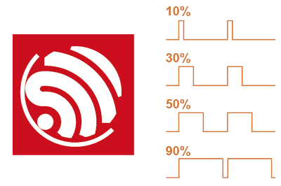
The duty cycle is defined as a value between 0 and 255 (or the maximum value defined by the resolution) that represents the percentage of time the pin will remain in a high state.
A duty cycle of 0 means the pin will always be low, while a duty cycle of 255 will keep the pin always high.
To set the duty cycle, we use the ledcWrite() function. Here’s an example of how to control the intensity of an LED connected to the PWM pin:
int dutyCycle = 128; // Duty cycle value (0 to 255)

ledcWrite(ledChannel, dutyCycle);
With a dutyCycle value of 128, the LED will receive approximately half of the maximum voltage, resulting in 50% brightness.
Code Example
Next, I’ll give you a complete example of how to control the intensity of an LED connected to an ESP32 PWM pin:
const int ledChannel = 0;
const int ledPin = 5;
const int frequency = 5000;
const int resolution = 8;

void setup() {
  ledcSetup(ledChannel, frequency, resolution);
  ledcAttachPin(ledPin, ledChannel);
}

void loop() {
  // Gradually increase the duty cycle to brighten the LED
  for (int dutyCycle = 0; dutyCycle <= 255; dutyCycle++) {
    ledcWrite(ledChannel, dutyCycle);
    delay(10);
  }

  // Gradually decrease the duty cycle to dim the LED
  for (int dutyCycle = 255; dutyCycle >= 0; dutyCycle--) {
    ledcWrite(ledChannel, dutyCycle);
    delay(10);
  }
}
In this example, the LED connected to pin 5 will gradually light up from the minimum to the maximum duty cycle and then fade back down.
Alternative Using a Library
Many people have gotten used to using analogWrite as part of their programs because of the convenience and simplicity it offers (you might even have many programs that use it and would like to use them on the ESP32).
Fortunately, you’re not the only one. So different authors have created libraries to allow using PWM like on a “classic” Arduino.
An example of such a library is GitHub - erropix/ESP32_AnalogWrite: Provides an analogWrite polyfill for ESP32 using the LEDC functions
#include <Arduino.h>
#include <analogWrite.h>

int brightStep = 1;
int brightness = 0;

void setup() {
  // Set resolution for a specific pin
  analogWriteResolution(LED_BUILTIN, 12);
}

void loop() {
  brightness += brightStep;
  if ( brightness == 0 || brightness == 255 ) {
    brightStep = -brightStep;
  }

  analogWrite(LED_BUILTIN, brightness);

  delay(10);
}
By using this library, we will lose some of the flexibility that using ledc directly offers, so it’s preferable to use the native method.
But, as a transition to adapt your programs, or if it’s simpler for teaching purposes (for example), using a library is not a bad option.
References: