The ESP32-S3 is the natural successor and flagship of the Espressif ESP32 family.
The first step before being able to use it must be to familiarize ourselves with its features and functionalities.
So, just as we did in this post with the traditional ESP32 model (without a version), in this post we are going to review the main points of its characteristics and hardware.
So let’s start with the technical specifications table of the ESP32-S3.
| Feature | ESP32-S3 Series |
|---|---|
| Launch year | 2020 |
| Core | Xtensa® dual-core 32-bit LX7 |
| Wi-Fi protocols | 802.11 b/g/n, 2.4 GHz |
| Bluetooth® | Bluetooth 5.0 |
| Typical frequency | 240 MHz |
| SRAM | 512 KB |
| ROM | 384 KB |
| External flash | Up to 1 GB device |
| External RAM | Up to 1 GB device |
| GPIO | 45 |
| ADC | 2x 12-bit SAR ADCs |
| DAC | ✖️ |
| Timers | 4x 54-bit, 3x watchdog |
| Temperature sensor | 1 |
| SPI | 4 |
| LCD interface | 1 |
| UART | 3 |
| I2C | 2 |
| I2S | 2 |
| LED PWM | 8 |
| Pulse counter | 4 |
| Touch sensor | 14 |
| Hall sensor | ✖️ |
| Camera interface | 1 |
If you are using an ESP32-S3, you have a similar summary in this post Which pins can I use on an ESP32-S3
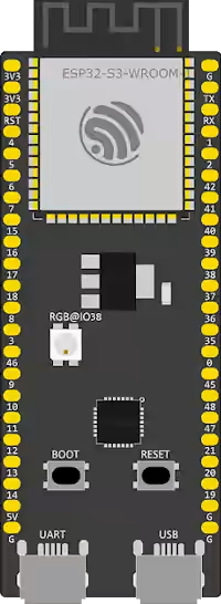
ESP32 Pinout
Now let’s look at the pinout diagram of the ESP32 from the official ESP32-S3 development board.
Legend and filtering
(click the buttons to show or hide pins)
- POWER
- GPIO
- ADC
- PWM
- DAC
- RTC
- TOUCH
- UART
- SPI
- I2C
- COMM
- CONTROL
- MISC
- Info
Keep in mind that these are the features of this specific board. The one you have on your device will depend on the SoM and the development board we are using.
If you have questions about what a SoC, SoM, and a development board are, consult this entry What is a SoC and a SoM
As always, if you have any doubts about your board, it is best to consult the official documentation from Espressif and, above all, the information from the device manufacturer.
Here is the link to the official documentation from Espressif about the Esp32-S3 DevKitc 1.
ESP32-S3-DevKitC-1 v1.1 - ESP32-S3 - — ESP-IDF Programming Guide latest documentation
Multiplexing
Pin multiplexing is one of the most important and useful features of the ESP32.
Basically, on the ESP32 we can reassign most of the GPIO functions to act on any pin, with little impact on performance.
Therefore, the values we will see are the default values, but generally, you can change them to others, as it suits you.
The RTC
The RTC (Real Time Clock) plays a fundamental role during Sleep modes. The RTC consists of the following parts:
- RTC controller (including timers and IO peripherals)
- RTC memory (fast and slow)
- Ultra Low Power (ULP) coprocessor
The ESP32 has 8 kB of SRAM in the RTC part, called fast RTC memory. The data stored here is not erased during deep sleep mode.
In addition, there are another 8kB of SRAM called slow memory, used for the ULP processor.
Digital Pins
GPIO Pins
The ESP32-S3 has up to 45 GPIO pins that can be assigned to different functions through programming.
Most of these digital GPIOs can be configured with internal pull-up or pull-down resistors.
Configuration (Strapping) Pins of the ESP32-S3
The ESP32 chip has the following configuration (strapping) pins:
- GPIO 0
- GPIO 45
- GPIO 46
These pins are involved in the configuration during startup. So avoid using them in your project.
More information in this entry read more
Input-Only GPIO Pins
These pins cannot be used as outputs, but can be used as digital or analog inputs, or for other purposes.
- GPIO 46
Additionally, unlike the other GPIO pins, they lack internal pull-up and pull-down resistors.
Interrupt Pins of the ESP32-S3
All GPIO pins can be configured as interrupts.
RTC GPIO Pins of the ESP32-S3
Some GPIOs are connected to the low-power RTC subsystem and are known as RTC GPIOs
- RTC_GPIO0 - GPIO0
- RTC_GPIO1 - GPIO1
- RTC_GPIO2 - GPIO2
- RTC_GPIO3 - GPIO3
- RTC_GPIO4 - GPIO4
- RTC_GPIO5 - GPIO5
- RTC_GPIO6 - GPIO6
- RTC_GPIO7 - GPIO7
- RTC_GPIO8 - GPIO8
- RTC_GPIO9 - GPIO9
- RTC_GPIO10 - GPIO10
- RTC_GPIO11 - GPIO11
- RTC_GPIO12 - GPIO12
- RTC_GPIO13 - GPIO13
- RTC_GPIO14 - GPIO14
- RTC_GPIO15 - GPIO15
- RTC_GPIO16 - GPIO16
- RTC_GPIO17 - GPIO17
- RTC_GPIO18 - GPIO18
- RTC_GPIO19 - GPIO19
- RTC_GPIO20 - GPIO20
- RTC_GPIO21 - GPIO21
These pins are used to wake the ESP32-S3 from deep low-power mode when the ultra-low power (ULP) coprocessor is running.
More information in this entry:
Touch Pins of the ESP32-S3
The ESP32-S3 has 14 capacitive touch GPIO pins.
- TOUCH1 - GPIO 1
- TOUCH2 - GPIO 2
- TOUCH3 - GPIO 3
- TOUCH4 - GPIO 4
- TOUCH5 - GPIO 5
- TOUCH6 - GPIO 6
- TOUCH7 - GPIO 7
- TOUCH8 - GPIO 8
- TOUCH9 - GPIO 9
- TOUCH10 - GPIO 10
- TOUCH11 - GPIO 11
- TOUCH12 - GPIO 12
- TOUCH13 - GPIO 13
- TOUCH14 - GPIO 14
When a capacitive load (such as a human finger) is near the GPIO pin, the ESP32-S3 detects the change in capacitance.
Enable (EN) Pin
Enable (EN) is the pin that controls the 3V3 regulator. It is configured with a pull-up resistor, so it connects to ground to disable the 3.3V regulator. For example, to reset the ESP32.
Analog Pins
PWM Pins of the ESP32-S3
The ESP32-S3 board has 8 PWM channels (all GPIO pins except the input-only pins) controlled by a PWM controller.
The PWM output can be used to control motors and digital LEDs.
ADC Pins of the ESP32-S3
The ESP32 integrates two ADCs and supports measurements on 20 channels
- ADC1_CH0 - GPIO 1
- ADC1_CH1 - GPIO 2
- ADC1_CH2 - GPIO 3
- ADC1_CH3 - GPIO 4
- ADC1_CH4 - GPIO 5
- ADC1_CH5 - GPIO 6
- ADC1_CH6 - GPIO 7
- ADC1_CH7 - GPIO 8
- ADC1_CH8 - GPIO 9
- ADC1_CH9 - GPIO 10
- ADC2_CH0 - GPIO 11
- ADC2_CH1 - GPIO 12
- ADC2_CH2 - GPIO 13
- ADC2_CH3 - GPIO 14
- ADC2_CH4 - GPIO 15
- ADC2_CH5 - GPIO 16
- ADC2_CH6 - GPIO 17
- ADC2_CH7 - GPIO 18
- ADC2_CH8 - GPIO 19
- ADC2_CH9 - GPIO 20
The ADCs are 12 bits, so we have 4096 (2^12) discrete levels, which translates to a precision of 0.8mV.
DAC Pins of the ESP32-S3
The ESP32-S3 does not include a DAC.
Communication Pins
UART Pins of the ESP32-S3
The ESP32-S3 development board has three UART interfaces: UART0, UART1, and UART2, supporting asynchronous communication (RS232 and RS485) and IrDA up to 5 Mbps.
The UART0 pins are connected to the USB-to-serial converter and are used for programming and debugging. It is not recommended to use the UART0 pins.
On the other hand, the UART is reserved for the integrated FLASH memory chip. The UART1 pins are reserved for the integrated flash memory chip.
So the best option is to use UART2 to connect UART devices.
I2C Pins of the ESP32-S3
The ESP32-S3 has a single I2C bus that allows connecting up to 112 sensors and peripherals. The SDA and SCL pins are default assigned to the following pins.
- SDA - GPIO 8
- SCL - GPIO 9
However, it is possible to use any GPIO pin to implement the I2C protocol using the command wire.begin(SDA, SCL).
SPI Pins of the ESP32-S3
The ESP32 has four interfaces SPI0, SPI1, SPI2, and SPI3. SPI0 is used to connect with the FLASH memory, and SPI1 for PSRAM (if the board has it). So it’s best to focus on SPI2 and SPI3.
| SPI | MOSI | MISO | CLK | CS |
|---|---|---|---|---|
| SPI2 | GPIO 35 | GPIO 37 | GPIO 36 | GPIO 39 |
| SPI3 | GPIO 11 | GPIO 13 | GPIO 12 | GPIO 10 |
SPI FLASH
These pins are connected to the integrated SPI flash memory in the ESP32-S3 chip. Do not use these pins in your projects.
- GPIO 26
- GPIO 27
- GPIO 28
- GPIO 29
- GPIO 30
- GPIO 31
- GPIO 32