
I continue to tell my stories about the garage door. We remember from the previous entries that a gear had broken, and I had been asked for 1100-1200€ to fix it.
I had made a replacement with 3D scanning and printing, almost tearing off the roof to discover that the problem was with the electronics, and I had decided to completely replace it with my own.
After several weeks of waiting, I have received my parts, and I have everything to assemble my setup. So I start with the assembly of my garage door opener.
Let’s get to work
With all the physical parts, I can now arrange how they will be assembled. I have to avoid the motor and the chain rail, and assemble everything around them. Of course, the original cover goes on top, so I have a height limitation. It fits tightly!
The power supply is quite large. I can only mount it in the middle, which limits the space for the electronics a lot.
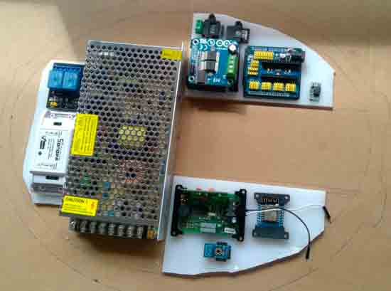
I decide to divide the assembly into two “wings” around the rail, in the available space. One part will have the Arduino, the motor controller, the encoder connection, and the magnetic limit switch. This is the “physical” control part, and it makes sense for it to be together.
The other part will contain the remote control receiver and the ESP8266 Wemos. This part is dedicated to “connectivity,” and I don’t mind that it is independent of the first. In addition, it operates at 24V and 3.3V, respectively, while the first one operates at 5V.
Finally, I have an additional add-on with the relay module for controlling the lights, and space to put a Sonoff if I find it interesting at some point. Not only do I not care that this part is independent, it is not even strictly necessary for the rest to work.
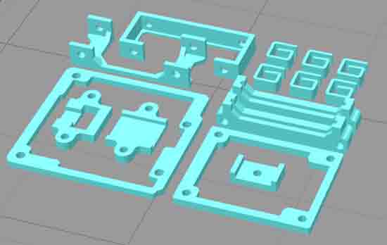
Shaping it on cardboard, I transfer the shape to plastic sheets and, using a Dremel, I cut out each of the assembly modules.
Next, I design and 3D print supports for each of the electronic components. I drill the plastic so that everything can be screwed together and be removable.
I solder all the connections and the electronics. In each connection between modules, I leave a prepared cable, playing with cable types and male and female connectors, so that it is impossible to connect anything incorrectly by mistake.
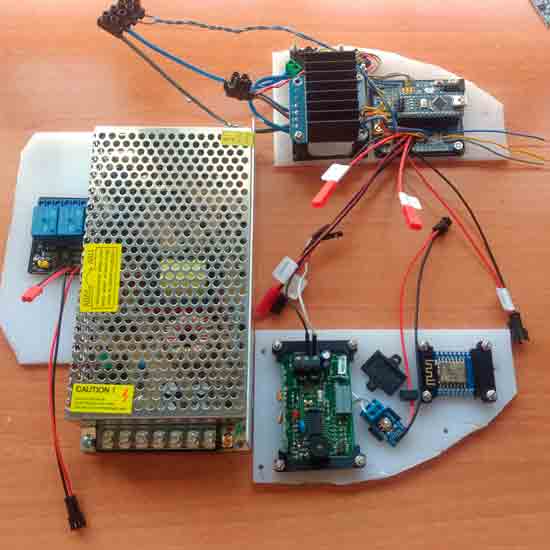
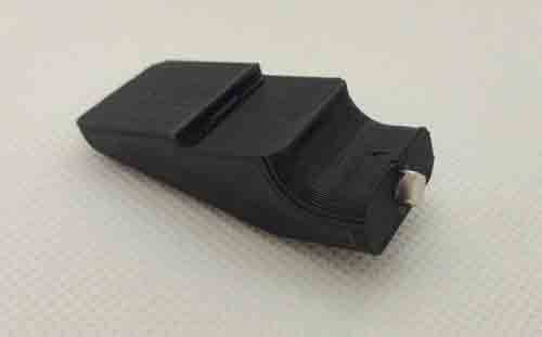
On the other hand, I design and 3D print a clamp for the rail, which will house the magnetic sensor. For the connection, I use an old keyboard cable. This way, I can run the 3 cables I need, at a distance of 1 meter (approx) from the electronics in a single shielded cable.
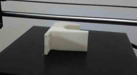
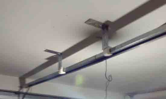
In addition, after the bad experience almost tearing everything off the roof, I design and 3D print some brackets so that the rail is better secured to the ceiling (which, in my opinion, should always have been and they avoided the work of putting them).
To attach them to the ceiling (I remember that I have polystyrene vaults), I use special plugs for plaster that, although they open a lot, are for low loads. I test the strength… well, it seems that they are well attached. They shouldn’t have to withstand much force, just prevent the rail from oscillating.
Finally, I design and 3D print a holder for the rail, which holds the magnetic sensor. The door will stop at the encoder steps, but if they fail, the door will stop about 5mm from the sensor, without reaching it. And even if everything fails, it will hit the holder and the encoder or current sensor will stop the movement. Safety first!
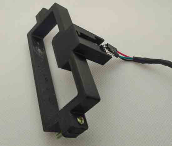
Finally, the magnetic sensor mechanism is completed with this support in which I insert a magnet at the tip, and fix it with assembly adhesive to the door-pulling carriage.
Loads of Measurements
With my electronics assembled, it’s time to start testing. I go down and connect everything, with a deployment of oscilloscope, multimeters, serial monitor, etc. I’m going to record more data than a space probe!
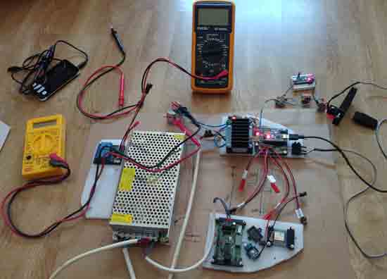
I start by testing that I control the movement of the door correctly. To start, as soon as I move the door, it tears off the new supports and part of the roof with them. Crap… well, I expected it to tear off the plugs. But well, I’ll take care of that later.
Now I have to record several cycles of opening and closing the door, without letting the door close completely. I’m going to store the intensities, the encoder steps, and the speed of the door (measured through the encoder).
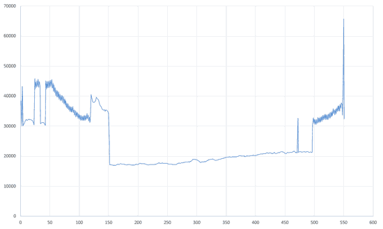
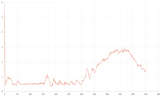
With this, I will have to adjust the denoise filters, the motor start peak filter, the tolerance for the anti-trapping safety mechanism… well, the whole control loop.
And while doing tests, suddenly… that “glan glan glan glan glan” sound again. Damn… The spare gear has broken. I take it apart and, sure enough, it has worn out the spline.
I’m back to square one. Worse, because I’m fed up, I’ve lost a lot of time, and I have a roof that looks like a sieve. Oh well, not every day is a win. To be continued (and finished) in the next entry.