Today we are going to see how to combine measurements from different IMU (inertial measurement unit) sensors to create an AHRS system that provides us with the orientation of a sensor, robot, or vehicle on a processor like Arduino.
We have talked a lot on the blog about IMUs, devices that combine accelerometers, gyroscopes, magnetic compasses and/or barometers to obtain sensors with 3, 6, 9 or 10 degrees of freedom.
So we saw in their day the basic entries How to use an accelerometer with Arduino, How to use a gyroscope with Arduino and Measure tilt with IMU.
Logically, the ultimate and most desired goal of this type of sensor is to create an AHRS (Attitude Heading Reference Systems), that is, a sensor that tells us the absolute orientation in the three X, Y, Z axes of the accelerometer.
Leaving aside altitude for a moment (which is only relevant for large height changes, i.e., basically for drones), obtaining orientation is a very frequent need and allows us to carry out a lot of interesting projects.
Some of them are participating in the sensor system for a robot’s guidance system, making a stabilizer, for example for a camera or a platform, self-balancing systems, among a bunch of projects of which you can find many examples just by searching on YouTube.
To see that the operation is correct, another very common initial example is to use the 3D visualization of a cube or prism, which moves on the screen with the same orientation as we set by rotating the sensor.
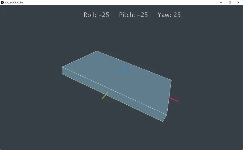
Precisely this is what we are going to do in this entry, set up an AHRS system with a 9DOF IMU sensor and visualize the measurements on the computer in a program made in Processing. Well then, let’s go for that little cube, for which we will need the RTIMULib-Arduino library.
The RTIMULib-Arduino Library
As we saw in the basic entries, obtaining orientation and an AHRS requires combining the measurements of the three individual sensors. We also saw that this is because each type of sensor has its own advantages and disadvantages, and contributes “something” (speed, stability, etc.).
To make an AHRS system we will need to combine the measurements by applying some kind of filter. In general, some type of Kalman filter, or simplified versions of it, is used. An example of a library that implements this type of filtering is Adafruit_AHRS https://github.com/adafruit/Adafruit_AHRS/
In general, this filter is a somewhat complex and heavy algorithm, so although several libraries exist, most occupy more space than an Atmega328P has available, so they cannot be used on Arduino Uno, Micro, or Pro, and we will need something superior like a Due.
Fortunately, one of the best libraries (probably the best) for performing AHRS on Arduino is RTIMULib-Arduino. Which, in addition to being one of the ones that gives the best results, even fits on an Atmega328p, consuming approximately 56% of the available space.
The RTIMULib-Arduino library is compatible with a wide variety of IMUs, including the most common ones in our projects such as the MPU-6050, MPU-9150, MPU-9250, L3GD20H + LSM303D and BNO055.
RTIMULib-Arduino is Open Source and its original code was in the repository https://github.com/luisllamasbinaburo/RTIMULib-Arduino, which has been deleted, as well as the blog where its news was reported.
Fortunately, copies of it are preserved, and here you have a clone of the repository https://github.com/luisllamasbinaburo/RTIMULib-Arduino where you can download (or contribute to) this great library.
Using the RTIMULib-Arduino Library
Configure the Library
To use the RTIMULib-Arduino library, first we must configure the sensor we are using and, if necessary, its I2C address. To do this, we have to go into the library’s “RTIMULibDefs.h” file and uncomment the sensor we are using.
Calibrate IMU
The next step is to calibrate the IMU’s magnetometer. We must repeat this process when we change the sensor (even if it is the same type). To do this, we load the following program.
#include <Wire.h>
#include "I2Cdev.h"
#include "RTIMUSettings.h"
#include "RTIMU.h"
#include "CalLib.h"
#include <EEPROM.h>

RTIMU *imu;                                           // the IMU object
RTIMUSettings settings;                               // the settings object
CALLIB_DATA calData;                                  // the calibration data

//  SERIAL_PORT_SPEED defines the speed to use for the debug serial port


#define  SERIAL_PORT_SPEED  115200

void setup()
{
  calLibRead(0, &calData);                           // pick up existing mag data if there

  calData.magValid = false;
  for (int i = 0; i < 3; i++) {
    calData.magMin[i] = 10000000;                    // init mag cal data
    calData.magMax[i] = -10000000;
  }

  Serial.begin(SERIAL_PORT_SPEED);
  Serial.println("ArduinoMagCal starting");
  Serial.println("Enter s to save current data to EEPROM");
  Wire.begin();

  imu = RTIMU::createIMU(&settings);                 // create the imu object
  imu->IMUInit();
  imu->setCalibrationMode(true);                     // make sure we get raw data
  Serial.print("ArduinoIMU calibrating device "); Serial.println(imu->IMUName());
}

void loop()
{
  boolean changed;
  RTVector3 mag;

  if (imu->IMURead()) {                                 // get the latest data
    changed = false;
    mag = imu->getCompass();
    for (int i = 0; i < 3; i++) {
      if (mag.data(i) < calData.magMin[i]) {
        calData.magMin[i] = mag.data(i);
        changed = true;
      }
      if (mag.data(i) > calData.magMax[i]) {
        calData.magMax[i] = mag.data(i);
        changed = true;
      }
    }

    if (changed) {
      Serial.println("-------");
      Serial.print("minX: "); Serial.print(calData.magMin[0]);
      Serial.print(" maxX: "); Serial.print(calData.magMax[0]); Serial.println();
      Serial.print("minY: "); Serial.print(calData.magMin[1]);
      Serial.print(" maxY: "); Serial.print(calData.magMax[1]); Serial.println();
      Serial.print("minZ: "); Serial.print(calData.magMin[2]);
      Serial.print(" maxZ: "); Serial.print(calData.magMax[2]); Serial.println();
    }
  }

  if (Serial.available()) {
    if (Serial.read() == 's') {                  // save the data
      calData.magValid = true;
      calLibWrite(0, &calData);
      Serial.print("Mag cal data saved for device "); Serial.println(imu->IMUName());
    }
  }
}
With the program loaded, we must rotate the sensor on the 3 axes, so that we cover the entire possible movement angle for the program to record the range of the measured magnetic field.
Each time the sensor expands the range, it shows it via serial port. So the process ends when, no matter how much we move the sensor, no new lines appear.
When we have finished the process, press the ‘Y’ key so that the recorded values are saved in the EEPROM. This way they will be available even if we restart or disconnect Arduino.
Get Measurements
With the magnetometer calibrated, we can start getting measurements from the IMU with the measurement of the three sensors combined with the fusion algorithm. To do this, we load the following program.
#include <Wire.h>
#include "I2Cdev.h"
#include "RTIMUSettings.h"
#include "RTIMU.h"
#include "RTFusionRTQF.h"
#include "CalLib.h"
#include <EEPROM.h>

RTIMU *imu;                                           // the IMU object
RTFusionRTQF fusion;                                  // the fusion object
RTIMUSettings settings;                               // the settings object


#define DISPLAY_INTERVAL 100

#define SERIAL_PORT_SPEED 115200

unsigned long lastDisplay;

void setup()
{
    Serial.begin(SERIAL_PORT_SPEED);
    Wire.begin();
    imu = RTIMU::createIMU(&settings);

    Serial.print("ArduinoIMU starting using device ");
  Serial.println(imu->IMUName());
  int errcode;
    if ((errcode = imu->IMUInit()) < 0) {
        Serial.print("Failed to init IMU: "); Serial.println(errcode);
    }

    if (imu->getCalibrationValid())
        Serial.println("Using compass calibration");
    else
        Serial.println("No valid compass calibration data");

    fusion.setSlerpPower(0.02);
    fusion.setGyroEnable(true);
    fusion.setAccelEnable(true);
    fusion.setCompassEnable(true);
}

void loop()
{
    unsigned long now = millis();
    unsigned long delta;

  int loopCount = 1;
    while (imu->IMURead()) {

        if (++loopCount >= 10)  // this flushes remaining data in case we are falling behind
            continue;
        fusion.newIMUData(imu->getGyro(), imu->getAccel(), imu->getCompass(), imu->getTimestamp());
        if ((now - lastDisplay) >= DISPLAY_INTERVAL) {
            lastDisplay = now;

      Serial.print(((RTVector3&)fusion.getFusionPose()).y() * RTMATH_RAD_TO_DEGREE);
      Serial.print(';');
        Serial.print(((RTVector3&)fusion.getFusionPose()).x() * RTMATH_RAD_TO_DEGREE);
      Serial.print(';');
      Serial.println(((RTVector3&)fusion.getFusionPose()).z() * RTMATH_RAD_TO_DEGREE);
        }
    }
}
When running it, we will see the Euler angles of the orientation measured by the IMU.
Show Results in Processing
And we come to the most “showy” part, which as we said was to check the operation of the IMU and the library by graphing the Euler angles in a program. For simplicity, we are going to do it in Processing, although of course we could do it in any other language.
Here is an example to display a prism that shows the orientation recorded by the IMU. Remember to change the port “COM4” to the one you are using.
import processing.serial.*;
import java.awt.event.KeyEvent;
import java.io.IOException;

Serial arduinoPort;
float roll, pitch, yaw;

void setup()
{
  size (1280, 768, P3D);
  arduinoPort = new Serial(this, "COM4", 115200);
  arduinoPort.bufferUntil('\n');
  }

void draw()
{
  drawBackground();

  rotateY(radians(-yaw));
  rotateX(radians(-pitch));
  rotateZ(radians(-roll));

  drawCube();
}

void drawBackground() {
  translate(width/2, height/2, 0);
  background(#374046);
  fill(200, 200, 200);
  textSize(32);
  text("Roll: " + int(roll) + "     Pitch: " + int(pitch) + "     Yaw: " + int(yaw) , -200, -320);
}

void drawCube() {
  strokeWeight(1);
  stroke(255, 255, 255);
  fill(#607D8B);
  box (500, 40, 300);

  strokeWeight(4);
  stroke(#E81E63);
  line(0, 0, 0, 300, 0, 0);
  stroke(#2196F2);
  line(0, 0, 0, 0, -70, 0);
  stroke(#8BC24A);
  line(0, 0, 0, 0, 0, 200);
}

void serialEvent (Serial myPort) {
  String data = myPort.readStringUntil('\n');
  if (data != null) {
    data = trim(data);
    String items[] = split(data, ';');
    if (items.length > 1) {
      roll = float(items[0]);
      pitch = float(items[1]);
      yaw = float(items[2]);
    }
  }
}
You have the code for the Processing viewer available on Github at this link. Depending on the IMU you are using, you may need to adjust the angles (change the order, invert the output).
The result is what you can see in the following video.
Download the Code
All the code from this entry is available for download on Github. 
