In previous posts, we have seen how to use Arduino’s digital outputs and PWM analog outputs to perform actions in the real world.
However, Arduino outputs are limited in both voltage and current. The maximum voltage they can supply will be the operating voltage (5V or 3.3V depending on the model). As for the maximum allowable current, it is 40mA, with a recommended value below 20mA.
Beyond turning on a small load or running a few example programs, the truth is that in the real world this is not enough to operate most loads, not even a small DC motor or a relay.
This behavior is common, in general, in all controllers. The function of a controller is not to provide sufficient current to perform actions. Its function is to read inputs, perform calculations, communicate with other controllers, and command actions.
Remember, the processor is the “brain” of a machine, not the muscle.
To perform actions, processors delegate to amplification stages or drivers, which act as adapters between the power level used in the controller and that required by the actuator.
One of the simplest and most common ways to perform this adaptation is the use of transistors. There are two main families of transistors. BJT transistors (bipolar junction transistor), which were the first to appear, and FET transistors (field effect transistor).
In this post, we will learn to use BJT transistors to handle larger loads than we can handle with Arduino’s digital or analog outputs.
In the next post, we will see how to do this with MOSFET transistors, a sub-family of FET transistors.
What is a BJT Transistor
Transistors are electronic devices that form the basis of modern electronics.
In a very summarized way, we find two different applications or modes of operation.
- Amplify an electrical signal
- Act as an electrically controlled switch
There are many models of transistors, each with different electrical characteristics, to meet the various needs of our electrical circuits. Therefore, an important part of the design phase when using a transistor is choosing the appropriate model.
Externally, the same transistor can be manufactured in different standard packages. Typically, larger packages allow for better heat dissipation and, therefore, can handle higher currents better.
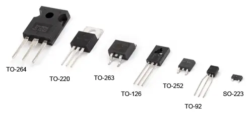
The packages we will use most frequently in our projects are TO-92 and TO-220.
Therefore, it is not possible to easily distinguish the characteristics of a transistor simply by visual inspection. We must look at the model number, engraved on it, and consult its corresponding Datasheet.
How a BJT Transistor Works
Transistors are relatively complex devices, and knowledge of electronics is required to understand them in depth. Therefore, instead of performing a detailed analysis, we will limit ourselves to providing a series of guidelines to understand their fundamentals and allow us to use them in our assemblies.
If you need more information, you can consult any electronics book, or feel free to leave a comment asking whatever you want.
A good way to understand how a transistor works is to look at its “grandfather” in electronics, the vacuum tube.
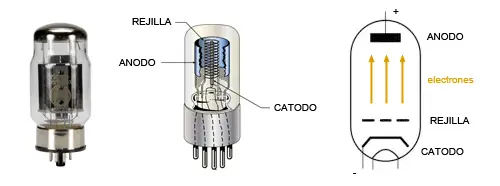
A vacuum tube is an electrical component that has three terminals inside a tube from which air has been evacuated. One of the terminals acts as a cathode and another as an anode. The third terminal is connected to a metal grid located between the two.
When electricity is applied to the grid terminal, an electric field is generated that “pulls” electric current from the cathode. The electrons travel through the vacuum, pass without hitting the grid, and finally reach the anode.
The result is that we have an “electrical contact” between the cathode and anode terminals, in which we can regulate the amount of electricity flowing between them by acting on the grid (the third terminal). With this, we achieve an electrical amplifier.
In BJT transistors, the glass bulb and terminals are replaced by junctions of semiconductors with different doping levels (hence their name, bipolar junction), forming a solid integrated circuit. This allows them to be made much smaller and more durable than vacuum tubes.
In a transistor, we also have three terminals, called Emitter, Collector, and Base. The “electrical contact” we are interested in is made between the emitter and the collector, while the base is the element that controls the amount of electricity flowing through the component.
Operating Modes in a BJT
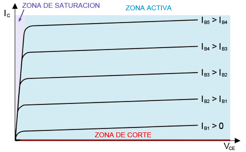
A BJT transistor has three operating modes.
- Cut-off: In this mode, the transistor behaves as if the collector and emitter were disconnected, so we say it is similar to having an open circuit.
- Saturation: In this mode, the transistor behaves as if the collector and emitter were connected by a low-voltage diode. That’s why we say it is similar to having a short circuit, with a certain voltage drop.
- Active: In this mode, the current between the collector and emitter is proportional to the base current.
The active mode is the mode used to amplify signals (for example, to make an audio amplifier). We will not use this mode in this post.
The cut-off and saturation modes can be used together to form an electrically controlled “switch”. It is these two modes that we will use to turn our load on and off, achieving an effect similar to using a physical switch, with the difference that this “switch” will be controlled by an Arduino output.
The state in which a BJT transistor operates depends on the current flowing through its base. For this reason, it is said that a BJT transistor is a current-controlled device (in contrast, vacuum tubes and FET transistors are voltage-controlled devices).
Connection Diagram
There is more than one way to connect the transistor. In this post, we will use the common emitter configuration, as it is the simplest for switching the transistor.
There are two sub-families of BJT transistors, the PNP type and the NPN type. The difference between them is the type of junctions and semiconductors used in their manufacture.
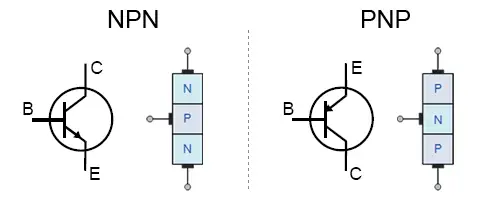
Mnemonic rule: You can use the word “Pincha” (which we will abbreviate as “PN”), imagining that the arrow is a needle that pokes or does not poke the inside of the transistor. If the arrow “Pokes” it’s PNP. If it “Doesn’t Poke” it’s NPN.
Both types of transistors, PNP and NPN, are similar in terms of construction and operation, but they differ in their application.
First, it influences the location where we have to place the BJT transistor in the assembly.
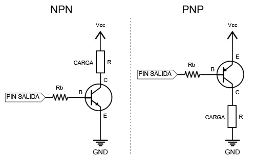
Mnemonic rule: The PNP (P) transistor is placed in the “Positive” part of the circuit. The NPN (N) transistor is placed in the “Negative” part of the circuit.
On the other hand, the NPN transistor conducts when VB is HIGH (greater than VE). However, a PNP conducts when VB is LOW (less than VE). Therefore, the output with a PNP transistor is an inverting output.
Finally, if Vcc is greater than VB (for example, with a 5V Arduino we try to switch a 12V load) we will not be able to switch the transistor because VB will never be greater than VE. And it’s better that way, because we would put Vcc on the Pin, and we could damage it. In that case, we would need pre-amplification, for example with an NPN.
Regarding the base resistor Rb, it serves to regulate the current flowing through the base of the transistor. Choosing its value is critical for the correct operation of the circuit. We will calculate the value of this resistor next.
Finally, it should be noted that not all transistor models and all packages assign the same terminals to each pin. Therefore, you will have to consult the pinout in the device’s Datasheet before making the assembly.
BJT Transistor Calculation
You can perform all these calculations that appear in this section automatically using the BJT Transistor as a Switch Calculator
To use the transistor as a switch, we are going to use the cut-off and saturation regions of the transistor, so we do not have to perform calculations in the active region.
In this way, the calculation is simplified and reduces to calculating the base resistance necessary for the transistor to switch between cut-off and saturation at the desired operating point.
In a BJT transistor, the current flowing through the collector Ic is proportional to the current in its base Ib. This relationship is called hFe (sometimes Beta). Typical values are between 100 and 200.
On the other hand, in saturation, the transistor behaves like a diode between collector and emitter with voltage Vce, and a diode between base and emitter with voltage Vbe.
For example, suppose we want to power a 200mA load with a nominal voltage of 12V, with a specific transistor whose Datasheet we have obtained that
- hFe(min) = 100
- Vce(sat) = 0.2
- Vbe = 0.7
In the example, we will assume a constant hFe, but in the real world, the hFe relationship varies between transistors of the same model, due to differences in the manufacturing process. Furthermore, it has dependencies with the operating temperature and the operating point. Therefore, in the component’s Datasheet, you will see curves of dependency for this factor.
Applying Ohm’s law to the device, we calculate that its equivalent is a 60 Ohm resistor.
Therefore, we can calculate the current flowing through the collector.
The current required at the base is the collector current reduced by a factor of hFe(min), so
Therefore, the required base resistance is less than
We choose the lower normalized resistor and would check by looking at the Datasheet curves that the base voltage is sufficient to drive the transistor into saturation.
Another way to ensure transistor saturation is to slightly increase the base current. In the example, Arduino has to provide less than 2 mA to the transistor, so we have room to increase the current a bit.
We would choose the closest normalized resistor. In this example, where we don’t have more details about the transistor, a 1k base resistor would be reasonable.
You can choose the closest normalized resistor with the Normalized Resistor Calculator
Finally, we must verify that all elements of the system are capable of handling the current and power flowing through them (including the resistors and the transistor itself)
Some transistor models allow for greater power dissipation by attaching an external heatsink.
BJT Models for Arduino
There is a wide variety of BJT transistors that we can use in our Arduino assemblies. In general, they are very cheap components. Their price varies depending on the model and characteristics, but a common price is 0.01 - 0.02€.
Among the many available models, some common ones are N2222, BC547, BC337, BC556, or TIP41C.
Connecting Inductive Loads
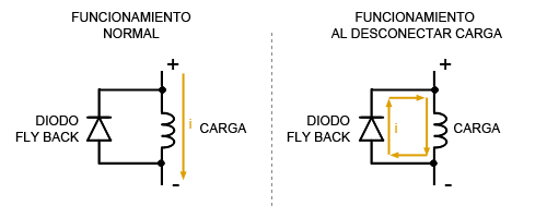
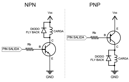
When connecting inductive loads, coils, electromagnets, motors, relays, we must add an additional protection device, the Flyback diode.
Inductive loads present an opposition to variations in the current flowing through them, for which they generate an induced current that opposes changes in intensity. These induced currents can damage the transistor or even the Arduino pin.
The flyback diode provides a low-resistance path that allows dissipating the induced currents from inductive loads, protecting the other devices.
Therefore, in the case of inductive loads, the assembly would look like this.
Darlington Pair
To obtain higher amplification ratios than those of a single BJT, we can use a Darlington pair, a device based on BJT transistors, widely used in electronics.
Essentially, a Darlington pair is a set formed by two BJTs in a single integrated circuit.
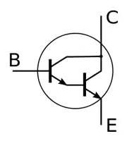
The overall behavior of a Darlington pair is similar to a BJT in which the hFEs are multiplied, reaching values of 5000-20000.
On the downside, the base voltage adds up, so typical Vce values are around 1.4V.
Similarly, there are multiple models of Darlington pairs. Their price is higher than that of a BJT transistor, but they are still cheap devices. The usual range is 0.10 to 0.20€.
Among the many available models, some common ones are the TIP140, BC317, and the ULN2003 integrated circuit, which has 7 Darlington pairs in a single IC.
BJT Transistors in PWM
BJT transistors are suitable for PWM outputs, so they can be controlled with Arduino’s analog (PWM) outputs.
The result will be a pulsed wave between Vcc and GND, with the same frequency as the PWM.
We only need to verify that the switching frequency of the chosen transistor is higher than the frequency of the PWM we apply.
Code Example
The code to use is exactly the same as we saw when covering digital outputs and PWM analog outputs in Arduino, so we refer you to the examples in those posts.
The transistor stage only allows us to adapt the output voltage and current to values higher than we could provide directly with Arduino’s outputs.