
In this post we saw how to create a homemade power supply from an ATX computer power supply. This is an essential addition to our amateur electronics and robotics projects as it provides multiple voltage outputs, with high stability and a huge output current, at a minimum cost.
Our ATX power supply provided voltages of 3.3V, 5V, and 12V, which are the most commonly used voltages in electronics. However, it is often necessary to have an adjustable voltage source whose output can be adjusted to any voltage value.
In this post, we will see how to expand our ATX power supply with a voltage converter module, which will allow us to have a complete adjustable voltage source with high current at a low cost.
In this first part, we will see the necessary materials and the project budget. In the next post, we will see the electrical diagram and finish assembling the power supply.
Operation
Our adjustable voltage source will have two outputs, one step-up and one step-down. We will power our new module with a 12V ATX power supply. This way, one of the outputs will allow us to work with voltages from 0.1V to 11V and the other from 11V to 35V. These two inputs, combined with those available in the ATX power supply, will give us enormous versatility for our projects.
Most of the project and budget is focused on two high-power DC/DC converters, capable of supplying 15A each. Of course, we can find cheaper converters (2A, 5A, and 10A) but, since this is a project we will use often, I consider it worthwhile to spend a little more money and make a high-power tool that is truly useful.
On the other hand, we will need 2 voltmeters to measure the voltage supplied by each stage. To power these voltmeters, we will use a low-power DC/DC converter. This way, we ensure that it is independent of the voltage outputs, which is useful, for example, so the displays do not turn off when working with low voltages, or do not get damaged by excessive voltage.
Finally, we will need a switch to turn off the power supply, potentiometers with their respective covers to modify the voltage, banana terminal connectors for both the input and the power supply outputs, and fuses, fuse holders, and diodes to protect our new adjustable voltage source.
Materials and Budget
The following image shows all the electronic components we need.
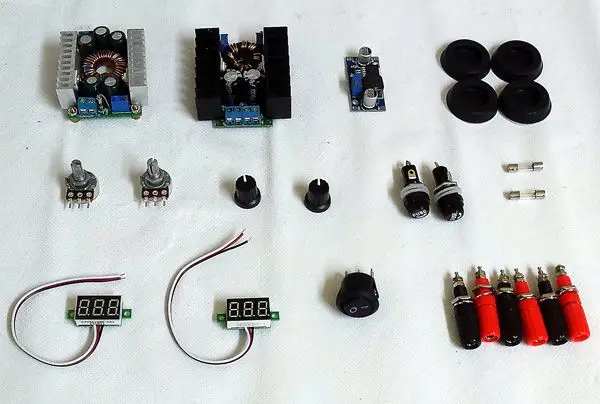 The total list of materials and prices is included below. All components can be easily purchased online.
- DC/DC STEP DOWN Converter (1 unit): €1.5
- 15A DC/DC STEP DOWN Converter (1 unit): €6
- 15A DC/DC STEP UP Converter (1 unit): €7.5
- 30V Voltmeters (2 units): €2.5
- Banana Connectors (6 units): €1.5
- 10K Potentiometer (1 unit): €1.2
- 50K Potentiometer (1 unit): €1.2
- Potentiometer Covers (2 units): €1
- Fuse Holder (2 units): €0.8
- 10A Fuses (2 units): €0.20
- 10A Diodes (2 units): €0.40
- Switch (1 unit): €1
That is, the total cost of our variable voltage module is around €20.
Plastic Enclosure
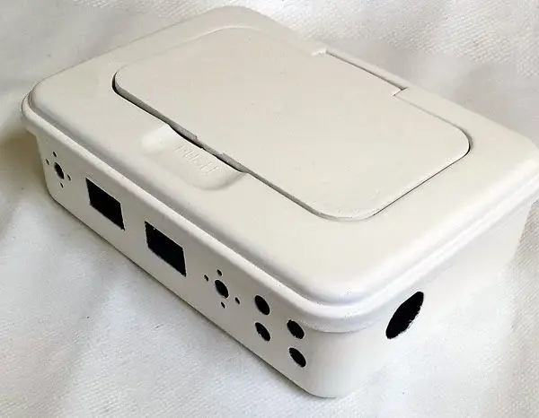
Finding a suitable box is going to be your first challenge. It is not easy to find a suitable box that fits everything we want to put in it without being excessively large, and that has a sufficiently long front to accommodate the displays and potentiometers.
In my case, I used a wipes box purchased from Carrefour a supermarket whose brand I will not mention. Here is my box before starting the assembly.
 Here we have the box after removing the stickers (which, by the way, took a lot of work), making the necessary holes to accommodate all the components, sanding, and painting it white with spray paint. This is the front view.
 And here is the rear view.
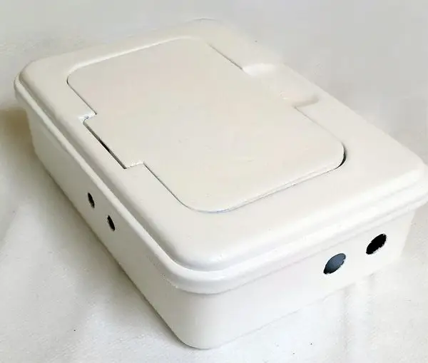 The exact arrangement of the components will depend on the box you use, but as a reference the box I used measures 190x135x50mm, and I assure you that it is quite tight in size.
In the next post we will see the assembly diagram, and we will finish the assembly.
