
In the previous entry we started assembling a power supply. We saw some basic aspects of ATX power supplies, the components needed for our project, and the total cost, which we estimated to be between 4 and 15 euros.
In this second entry, we are going to finish the project and carry out the assembly of the power supply. To do this, we will start by presenting the necessary diagrams.
Assembly Diagram
The following image shows the assembly diagram of the power supply we are going to build (you can click on any of the images in this post to enlarge them). 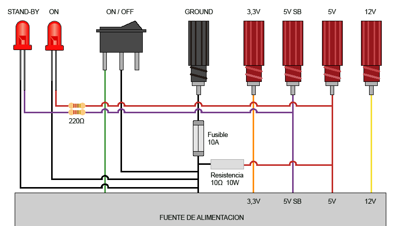 First, we install outputs using banana plugs for the voltage levels we are interested in. In my case, as I explained in the previous entry, they are 3.3V, 5V SB, 5V, and 12V.
On the other hand, we take the ground conductor to the corresponding banana plug and protect it with a fuse. Ideally, we would protect each of the outputs with its own fuse holder, but it would need a lot more space. This solution is much more functional and compact. Initially, I used a 10A fuse because it is sufficient for most uses. It can always be replaced temporarily by one with a higher capacity if needed for a specific application.
It is important to note that the function of this fuse is not only to protect the power supply from short circuits, it is also to protect the cables and other components from overheating. Keep in mind that the fact that your power supply can deliver 20 or 30A does not mean that the cables can withstand it. When assembling your power supply, pay special attention to this point, and calculate that each conductor can withstand about 10A. If you are going to use a higher current, you must use more than one conductor in parallel.
Continuing with the connection diagram, the Green cable (PS-ON) is the power-on conductor. When connected to ground, the power supply turns on. Therefore, we take the PS-ON cable to ground using a switch which will allow us to turn the power supply on and off.
On the other hand, we have two LEDs for monitoring the status of the power supply. One of them is connected to the 5V SB output, so it will light up when the power supply is connected to the power grid. The other one is connected to the 5V output, it will light up when the power supply is turned on. Both LEDs must be connected through a 220 to 330 Ohm resistor, since if they were connected directly to 5V, they could be damaged.
Finally, as we mentioned in the previous entry, certain power supplies may need a 10 Ohm, 10W resistor. The purpose of this resistor is to generate a load that prevents the power supply from entering Stand By mode. However, with the assembly diagram we are using, it is normal that we do not need this resistor and, in general, we can do without it. In case your power supply model goes into Stand By mode and you need this resistor, we would mount it between any red (5V) and black (GROUND) cable, as indicated in the diagram.
Assembly Process
To assemble, we can house the components inside the power supply case, or in an adjacent plastic box. In my case, I prefer to use a plastic box. It is easier to handle when making holes and facilitates future maintenance or modifications. Also, in case of a malfunction (for example, if one of the conductors comes loose) the possibility of a short circuit is reduced.
The only component I recommend mounting inside is, precisely, the 10W resistor that we probably do not need. This would be located inside the power supply tied with ties to one of the metal heat sinks, so that it is properly cooled by the air flow of the power supply.
In my case, I am going to use an old floppy disk drive case to house the components and wiring. In the following image, you can see the case, in which I have already made the perforations to house the components. 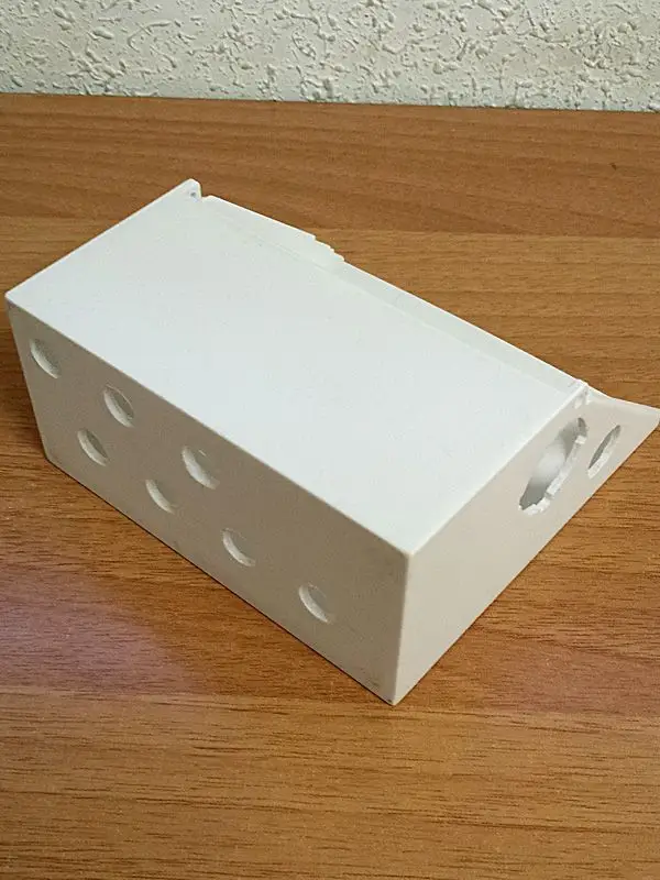 Here we see the case with the components already mounted in place.
 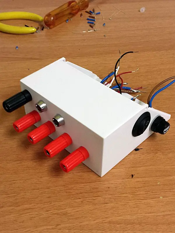 Here we can see the interior wiring. Note how I have taken two identical cables in parallel to each banana plug, in this way I divide the electrical intensity that each conductor supports. In theory, with the thickness of the cable I used and the duplicated line, this assembly should support 30A, although, as I said, it is protected by a 10A fuse for greater peace of mind.
 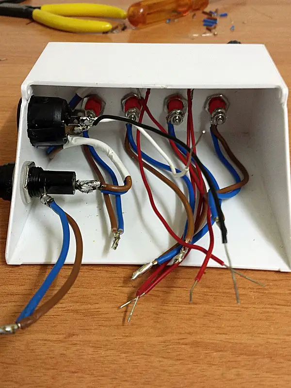 Next, I’m going to put the connector that will join the wiring of the case with the power supply.
 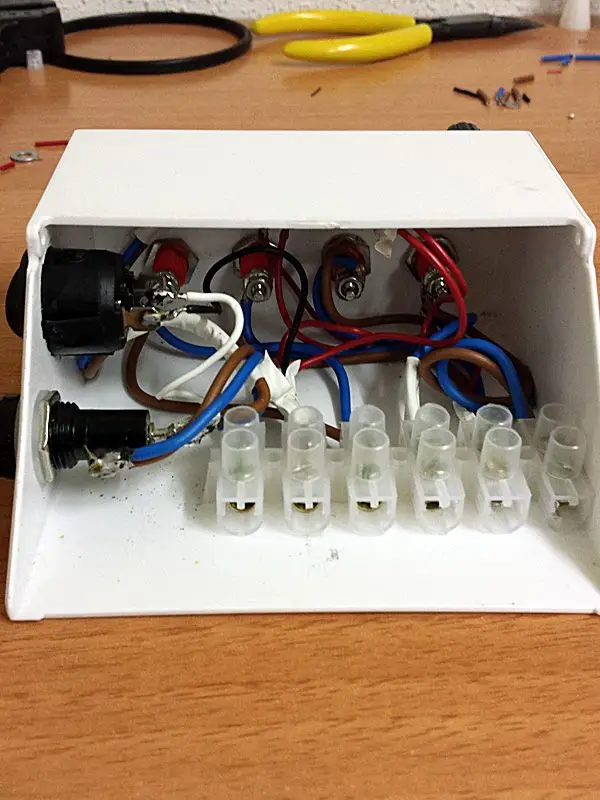 Inside the power supply, we cut and tape the cables that we do not need.
 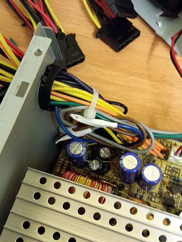 We connect the cables with the connector. Use all the available cables in the ATX connector, as seen in the image, grouping all cables of the same color. The goal, once again, is to divide the intensity among all the available cables.
 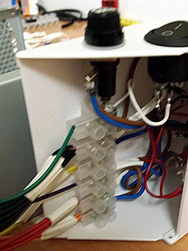 Next, we put rubber feet on the power supply to prevent it from slipping, and to match the height with the disk drive case.
 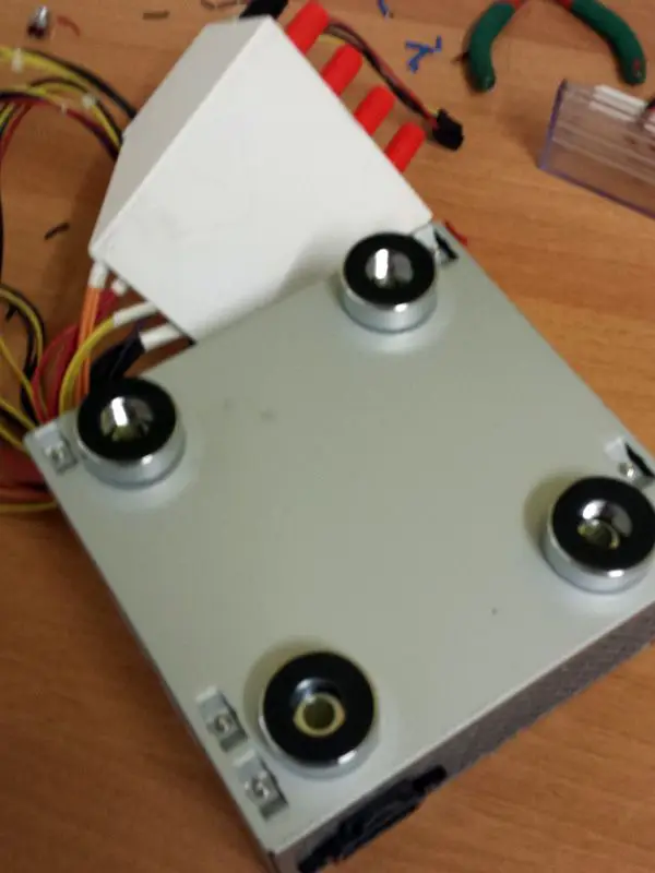 Finally, we glue the case to the side of the power supply, and check the correct operation of the switch, LED, and voltage outputs, measuring the voltage with a multimeter.
 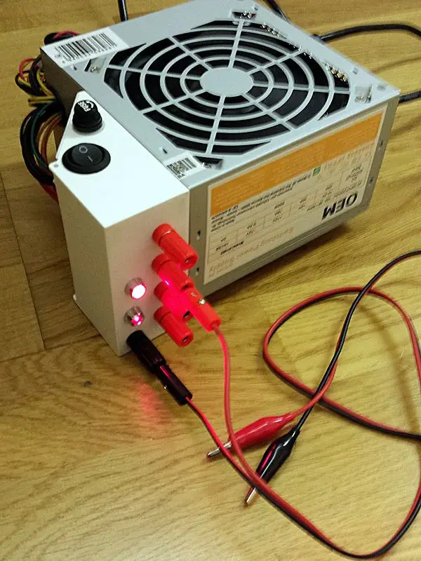 Here we have the final assembly with the transparent cover of the case already installed.
 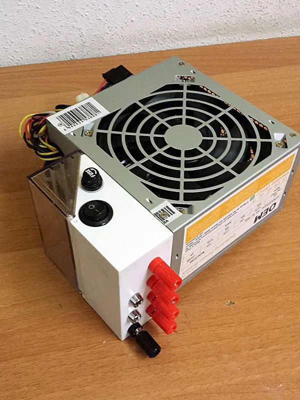 Here we see the back. I have tied the rest of the conductors with wires, in case I want to add a quick power connector for a motor, robot, etc. at some point.
 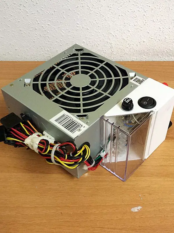 Assembly finished! We now have a high power, multiple voltage output power supply with high stability, for a budget of 5 to 15€, which will be our best ally in our future electronic projects.