We continue with the posts in the 3D printing section by looking at how the kinematics of an FFF 3D printer work.
In the previous post we saw that in an FFF printer, an extrusion head deposits molten filament in layers, resulting in the final 3D model.
As we hinted, most of the “trick” of the printer is knowing how to position the head relative to the bed with high precision. And in this post, we are going to see ways to achieve this by understanding the kinematics of the 3D printer.
This is useful for understanding how our 3D printer works, for knowing how to repair it or what is failing, and finally, in case one day you decide to build your own 3D printer.
Actually, this need for relative movement of the head is not exclusive to 3D printers. On the contrary, it is common to any CNC machine. From a small 2D milling machine to a large industrial laser.
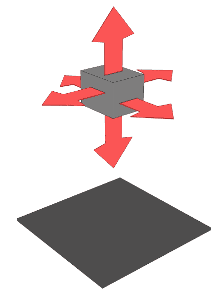
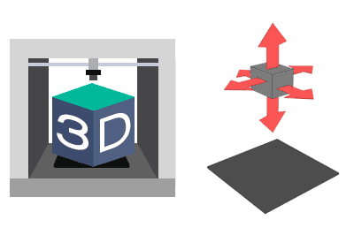
In the case of 3D printers, we are dealing with a 3-degree-of-freedom CNC, corresponding to displacement along the X, Y, and Z axes. Other machines may have fewer degrees, like a 2D milling machine, or more if rotational degrees are incorporated.
But getting the head to move relative to the bed does not mean the head has to have all the movements. In fact, this would not be practical and would overcomplicate the mechanism. It is common in any CNC machine to “transfer” part of the movement to the base, in our case, to the heated bed that will support the part.
So, let’s look at a couple of the most commonly used possibilities or configurations for solving the kinematics of 3D printers.
X - Y Degrees on the Head
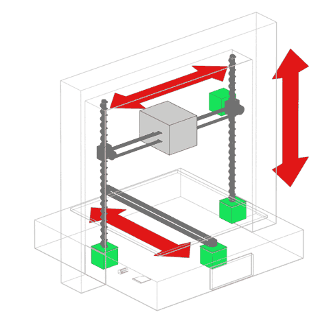
One possible configuration is to use two degrees of freedom (X and Y) on the head and leave the Z axis for the heated bed.
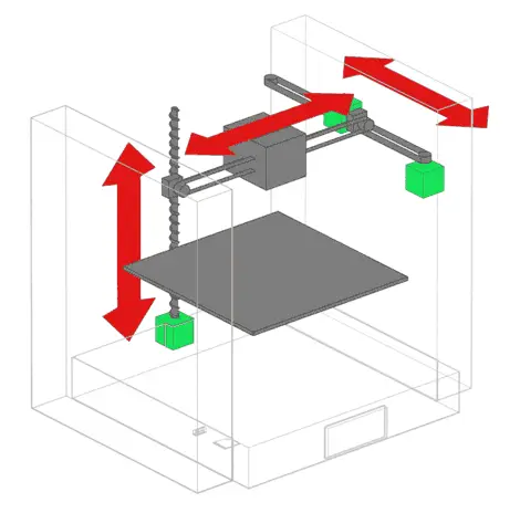
In this type of machine, the head moves in the horizontal X-Y plane, while the bed moves up and down. The head motors are fixed to the structure at the top of the body, and pulleys are used to move the head.
On the other hand, the bed motor is usually located at the bottom of the machine. Mechanisms are used to guide the bed’s movement, typically one or more rods.
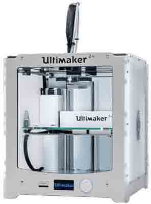
An example of a 3D printer that implements this configuration is the famous Ultimaker 3D.
X - Z Degrees on the Head
Another example of a kinematic configuration, probably the most popular among home printers, is to have two degrees of freedom, X and Z, on the head, and the Y axis on the bed.
In this way, the head moves up and down, in addition to moving horizontally. Meanwhile, the bed moves in and out of the machine. The head moves horizontally via a pulley, which is driven by a motor at one end.
To raise the entire assembly, motors are located at the bottom of the machine. A dual motor is often used to prevent the entire assembly from tilting and pitching.
Finally, the bed is moved by another motor located at the base. The movement is guided by rails or rods with bushings.
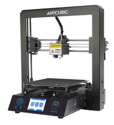
An example of a 3D printer that implements this configuration is our beloved Anycubic I3 Mega.
Conclusion
Of course, other configurations are possible. However, in general, these are the most common and work quite well.
Now comes the golden question: What is the best configuration for a printer? And the answer is that in theory, on paper, both are identical.
In reality, the performance depends more on the construction of the machine. For example, if the structure is robust, if it is metal or plastic, if the movement is properly guided, if dual motors are used on the axes, and the quality of the materials and their tolerances.
Now that we’ve seen how the kinematics of our FFF 3D printer works, it’s time to delve into its parts and components. And, precisely, this is what we will dedicate the next two posts to. See you soon!