
We are taking a short break from the entries about the ESP8266 and ESP32 as a server to look at one of the most interesting features: OTA programming.
The example is oriented to ESP32. In many cases it can also be adapted to ESP8266 by changing libraries and a few pin details.
In previous entries, we have seen the connection modes of the ESP8266 (AP, STA), the ESP8266 acting as a client, and several entries with the ESP8266 as a server.
OTA (Over The Air) programming is a very interesting feature that allows us to upload the firmware or SPIFFS files of the ESP8266 via a Wi-Fi connection, instead of the usual serial port.
This allows us to reprogram the ESP8266 without physical access, or the need to connect to the module with a cable. Of course, it is a very interesting feature when we place one of these modules in a permanent installation (imagine it’s behind a piece of furniture, inside a box, or stuck to the ceiling…)
Fortunately, OTA programming is very easy thanks to the ArduinoOTA library, which is also integrated into the hardware definition of the ESP8266 that we installed to be able to program the ESP8266 from the Arduino IDE.
OTA programming can be done from the Arduino IDE itself, from IDEs based on it (Visual Studio Micro, Visual Studio Code, PlatformIO…) or directly via the Web. In this entry, we will see the first one, from the Arduino IDE itself.
For OTA programming to work on the ESP8266 in the Arduino IDE, Python must be installed. If you haven’t done it yet, here is a tutorial.
Furthermore, for OTA programming to work, the ESP8266 must have double the memory occupied by the program we are going to upload. This is because, for safety, the program is uploaded to memory temporarily. When the upload is finished, it is dumped to the flash memory.
Arduino OTA Library
As we said, the “magic” of WiFi programming lies in the Arduino OTA library, which has all the functions we need to manage the process.
First, it is necessary to initialize the library with the function
//Starts the ArduinoOTA service
void begin(bool useMDNS = true);
Later, in the main loop we must call the function that handles the OTA if a programming request is received.
//Call this in loop() to run the service. Also calls MDNS.update() when begin() or begin(true) is used.
void handle();
On the other hand, the library provides different callback functions when certain events occur in the OTA process.
//This callback will be called when OTA connection has begun
void onStart(THandlerFunction fn);

//This callback will be called when OTA has finished
void onEnd(THandlerFunction fn);

//This callback will be called when OTA encountered Error
void onError(THandlerFunction_Error fn);

//This callback will be called when OTA is receiving data
void onProgress(THandlerFunction_Progress fn);
Sometimes, it can be important to add actions in these events. For example, in the case of a machine controlling a process, it will be “suspended” while the OTA reprogramming takes place.
Therefore, it would be necessary to add the appropriate actions so that the process develops safely (for example, stopping the motors, or moving the machine to a safe position).
Additionally, the ‘getCommand()’ function is available, which works while the OTA process has started, allowing us to distinguish if the OTA process is for the firmware (Flash) or the file system (FS).
//Gets update command type after OTA has started. Either U_FLASH or U_FS
int getCommand();
Another important issue is related to security because, logically, in many cases we do not want just anyone to be able to reprogram our board. Therefore, the ArduinoOTA library allows adding a password to authenticate the OTA process.
//Sets the password that will be required for OTA. Default NULL
void setPassword(const char *password);

//Sets the password as above but in the form MD5(password). Default NULL
void setPasswordHash(const char *password);
Finally, the library provides the following functions related to OTA,
//Sets the service port. Default 8266
void setPort(uint16_t port);

//Sets the device hostname. Default esp8266-xxxxxx
void setHostname(const char *hostname);
String getHostname();

//Sets if the device should be rebooted after successful update. Default true
void setRebootOnSuccess(bool reboot);
OTA Programming Example
Once we have seen the ArduinoOTA library in detail in its implementation for the ESP8266, it’s time to see it all with an example. As usual, we are going to split the code into files to improve reusability and maintainability.
Our main Sketch becomes as simple as
#include <WiFi.h>
#include <ArduinoOTA.h>

#include "config.h"  // Replace with your network data
#include "ESP32_Utils.hpp"
#include "ESP32_Utils_OTA.hpp"

void setup(){
  Serial.begin(115200);

  ConnectWiFi_STA();

  InitOTA();
}

void loop(){
  ArduinoOTA.handle();
}
A file called ‘ESP32_Utils_OTA.hpp’. This file contains all the repetitive logic of the OTA process.
void InitOTA()
{
// Port defaults to 8266
// ArduinoOTA.setPort(8266);

// Hostname defaults to esp8266-[ChipID]
// ArduinoOTA.setHostname(hostname);

// No authentication by default
// ArduinoOTA.setPassword("admin");

// Password can be set with it's md5 value as well
// MD5(admin) = 21232f297a57a5a743894a0e4a801fc3
// ArduinoOTA.setPasswordHash("21232f297a57a5a743894a0e4a801fc3");

ArduinoOTA.onStart([]() {
  String type;
  if (ArduinoOTA.getCommand() == U_FLASH) {
    type = "sketch";
  } else { // U_SPIFFS
    type = "filesystem";
  }

  // NOTE: if updating SPIFFS this would be the place to unmount SPIFFS using SPIFFS.end()
  Serial.println("Start updating " + type);
});

ArduinoOTA.onEnd([]() {
  Serial.println("\nEnd");
});

ArduinoOTA.onProgress([](unsigned int progress, unsigned int total) {
  Serial.printf("Progress: %u%%\r", (progress / (total / 100)));
});

ArduinoOTA.onError([](ota_error_t error) {
  Serial.printf("Error[%u]: ", error);
  if (error == OTA_AUTH_ERROR) {
    Serial.println("Auth Failed");
  } else if (error == OTA_BEGIN_ERROR) {
    Serial.println("Begin Failed");
  } else if (error == OTA_CONNECT_ERROR) {
    Serial.println("Connect Failed");
  } else if (error == OTA_RECEIVE_ERROR) {
    Serial.println("Receive Failed");
  } else if (error == OTA_END_ERROR) {
    Serial.println("End Failed");
  }
});

ArduinoOTA.begin();
Serial.println("");
Serial.println("OTA iniciado");
}
Result
We load the program onto the ESP8266 as usual, via the serial port. Now, we can unplug the cable from the computer and leave it connected only to a power source (for example, a phone charger, a battery, etc…)
On the other hand, we restart the Arduino IDE. Upon restarting it, we will see that we have a new programming “port”.
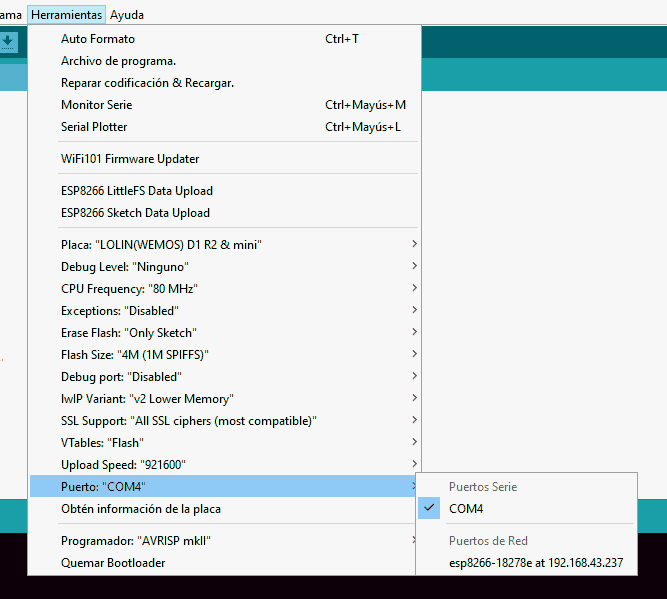
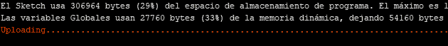
We select this WiFi programming port and upload the file again. We will see that the process is displayed correctly in the Arduino IDE.
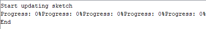
And, if we had the ESP8266 connected to a computer, we would see the serial output also indicating the process.
It is important to remember to add the OTA functionality in the new firmware we upload or we will lose the OTA programming capability.
That easy! In general, the process is quite simple and very robust (it has never failed me). Now you can use WiFi programming to test your examples, uploading both firmware and SPIFFS files.
In the next entries, we will delve into the functionalities of the ESP8266 as a server, learning how to send data from the client to the ESP8266 through a form.
Download the Code
All the code from this entry is available for download on Github.

Version for ESP8266: https://github.com/luisllamasbinaburo/ESP8266-Examples
Version for ESP32: https://github.com/luisllamasbinaburo/ESP32-Examples