We continue with the 3D design and printing section, diving right into CAD software with this introduction to handling CAD programs.
In previous posts, we have already seen the main types of 3D drawing software, and the main existing CAD software, highlighting those that are Open Source or free, which are the ones we will normally use in the Maker realm.
As we said, it’s finally time to get into CAD software, which is the main type of 3D software that most of us will use most of the time for part design (unless you are in fine arts and know how to sculpt a dragon’s head).
To do this, we are going to make an introduction to the philosophy and generalities of CAD software, presenting some common concepts and terms in the field.
It’s important to note that we are not going to focus on any specific CAD program. Firstly, because there are many CAD programs, and you will surely find hundreds of tutorials and documentation for each one.
That’s not what we want. What we want is to get some “culture” of the 3D world and learn to use CAD software, not ONE CAD program. And that’s because, at their core, the philosophy and concepts behind all of them are the same.
Of course, each program will have its own peculiarities. But in most cases the operation of all of them is very similar. If you know how to use one CAD software, switching to another is no longer a matter of “how on earth do I do this” but rather “where is the button that does this thing I know I want to do.”
So, let’s present the general philosophy of CAD software and the terms we will encounter when we open any CAD software. And then, let everyone use the one they like the most, have available, or know how to use.
Elements of CAD Design
Typically, in CAD programs, a distinction is made between parts, assemblies, and drawings. In many of them, there are different file extensions for each, although not in all cases.
Next, we will see each of these elements.
Parts
The part is the fundamental component of our designs. They represent the abstraction of a single object and correspond to a physically manufacturable part.
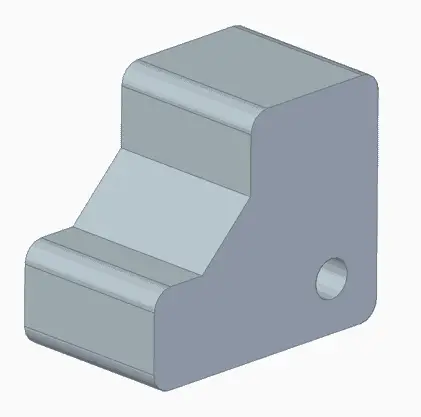
Therefore, in general and with rare exceptions, they will consist of a single connected volume. Furthermore, they will have a material and physical properties such as mass, center of gravity, axes of inertia, etc.
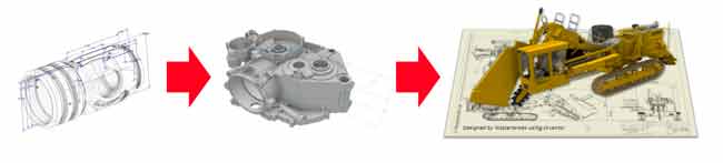
During 3D design, a very important part of our time will be spent drawing and modifying parts. Most of the time we will start from a 2D drawing and convert it into 3D using solid or surface operations. Let’s look at this in a bit more detail next.
2D Sketch
In CAD programs, the 2D part of the design is generated through sketches that we create on a reference plane.
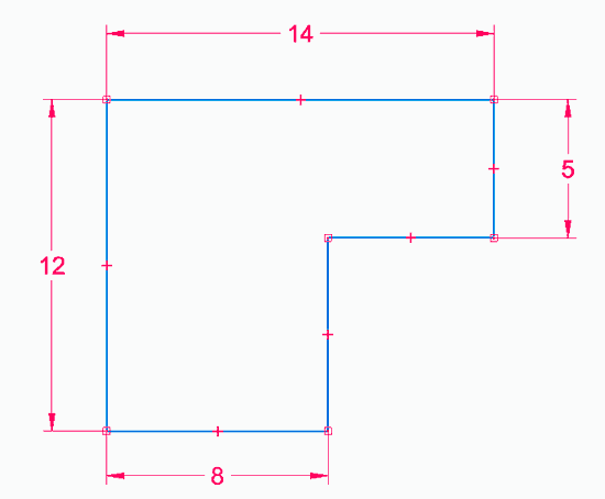
The entities we draw maintain relationships and constraints between them. Such as being horizontal/vertical, parallel, perpendicular, concentric…
The dimension of the elements is also considered a constraint. Therefore, sketches are normally drawn “approximately” without paying special attention to size, and later dimensioned using constraints.
If you are used to technical drawing programs like AutoCAD, where entities are drawn directly with their dimension, you might find this way of drawing a bit difficult at first (don’t worry, it happened to all of us).
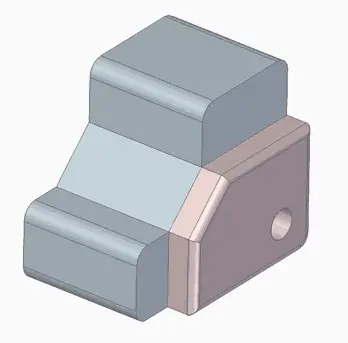
3D Operations
The next step is to use the 2D Sketches to generate 3D solids through operations. There are many operations we can use, although we will see in due course that there are actually not as many as they seem at first.
Knowing the available operations and mastering their use is key to using CAD software, and even more so for using more than one CAD. Given their importance, we will dedicate the next post exclusively to seeing the 3D operations available in CAD programs.
Assemblies and Subassemblies
Once we have the parts, it is normal to combine them into an assembly. For this, positioning constraints are used, such as coincidence, contact, insert, and many others like axis on plane, cam constraint, helical.
The list of parts and the quantity constitute the “Bill of Materials”. It is an important element as it represents the list of components needed to manufacture the object, it is closely related to the part’s budget, stocks, links with the ERP, etc.
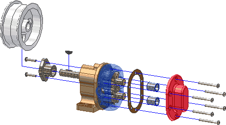
On the other hand, in many cases we can leave some of the parts not fully constrained, so they retain some degree of freedom. This allows animating or simulating the kinematics of the assembly.
Drawings
Finally, CAD programs allow us to create 2D drawings and representations of the parts and assemblies we create. The process is very similar in all CAD programs.
First, there are tools to add a main view of a part or assembly according to some orientation. Then we add auxiliary views, sections, cuts, details. And on them we dimension, add symbols or annotations.
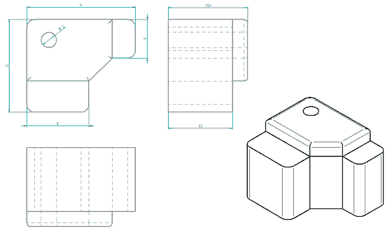
In the maker field, in general, this may not be such a widely used functionality. Even in the professional world, it is a trend that is disappearing in favor of manufacturing with 3D viewers.
Parametric Associative Design
Perhaps the most notable feature of CAD programs is their associative and parametric nature. In fact, we often refer to CAD software as “associative drawing” or “parametric drawing”.
This means that all operations maintain a dependency on the previous ones. In this way, if we modify a previous operation, all subsequent ones are maintained and reflect this modification.
Logically, for this to happen, the modification must allow the subsequent operations to remain valid. For example, if we chamfer a hole and later modify the hole, the chamfer operation is “lost” and is no longer valid.
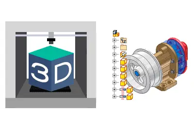
Operation Tree
In practically all CAD programs, operations are reflected in order in an operation tree.
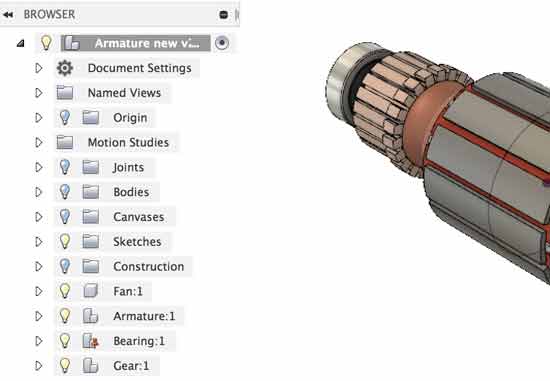
This way, we can comfortably visualize the steps the design has undergone and their dependencies. Thus we can modify operations, return to previous states, or even temporarily deactivate an operation.
Variables and Parameters
The other related and common feature in CAD programs is the possibility to define variables and parameters in parts.
For example, in a part, instead of creating a part with a length of 100 mm, we can define a variable L, and use this value as if it were a numerical value.
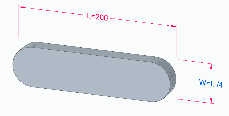
At any time, we can modify the value of this variable and the entire design will be modified accordingly.
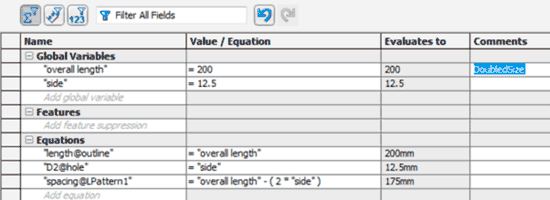
On the other hand, we can define relationships or equations between variables. This allows us to give a certain “intelligent” behavior to our designs, facilitates their modification, and helps eliminate errors.
Additional Features
In addition to these “traditional” features, most CAD programs have evolved to incorporate more advanced features that facilitate part design.
These features are becoming more and more frequent (or even common) in CAD, so let’s review some of these concepts so you are not caught “off guard” when you encounter them.
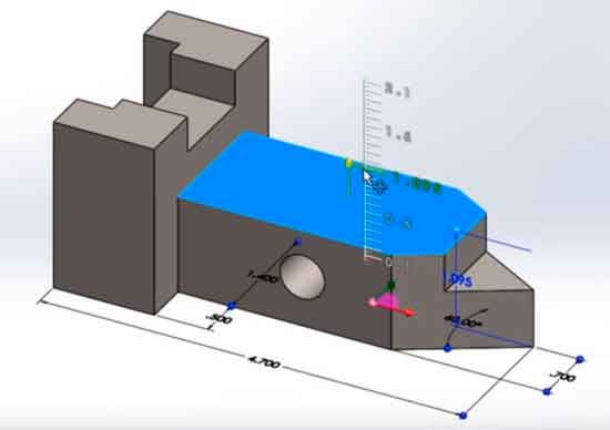
Direct Modeling
One of these features is the capacity for direct editing, understood as the possibility of modifying a part simply by clicking on a face or operation and dragging.
For example, we have Instant 3D in SolidWorks, synchronous mode in Solid Edge, or Direct 3D in Inventor. Although each software incorporates direct modeling with its own peculiarities.
Top-Down Design (Design from Assembly)
A basic functionality of any modern CAD is the ability to create parts directly from an assembly. This facilitates the quick creation of parts, especially when they are related in an assembly.
These parts can either be published as a normal part file or, in some cases, remain “embedded” in the assembly without having their own file.
Another common need is the ability to create relationships between parts through their assembly in a set. For example, we can project elements from one part onto another, to perform machining in the appropriate position so that it fits with another.
This generates dependencies and relationships between the part files, so although it is very useful, you always have to pay attention when using it.
Adaptive Parts
The concept of an adaptive part refers to a part that can be inserted into an assembly and modify some of its parameters. This variation of the parameter is done without modifying the original part, nor the need to create an independent file.
As examples of implementations in CAD, we have adaptive parts in Solid Edge or iParts in Inventor.
Part Families
Related to the previous one and, in a way, totally opposite. Part families are multiple files that are generated by varying one or more parameters. In this case, each variation generates its own “child” file.
Part families are used to quickly generate similar elements, for example, those that vary in a nominal length.
Furthermore, they allow for easier maintenance of these parts. To make a modification, we only modify the “parent” file, and depending on the CAD, we either regenerate the children or they are updated automatically.
As examples of implementations, in Solid Edge they are called Part Family, or in Inventor they correspond to iAssemblies.
Associated Features
Another common functionality is the possibility for one part to perform operations on others. For example, it is useful for parts like inserts that require machining for their assembly, or to avoid repeating machining that we do frequently.
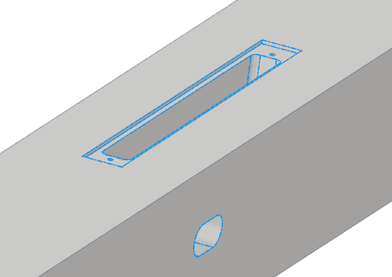
For example, we have Library features in SolidWorks or iFeatures in Inventor.
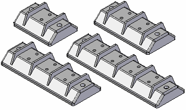
Multi-Body / Multi-Part
An increasingly common feature is multi-body or multi-part design. It consists of having several independent volumes within the same part file.
This allows drawing them quickly, using the available part operations. Subsequently, the multi-part objects are published, and a part file is generated for each body, and an assembly file that assembles them according to the original arrangement.
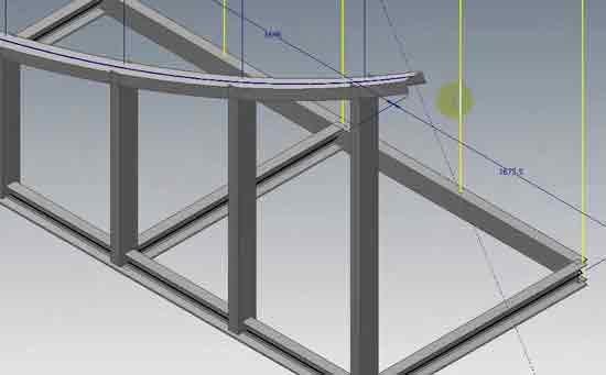
Multi-body design represents a speed improvement in the case of assemblies with a large number of parts that have a strong relationship with each other. For example, in welded frame structures.
Conclusion
In this post, we have seen some of the fundamentals of CAD design. Knowing these concepts will allow us to handle one or several CADs easily.
We have seen the main traditional characteristics of CAD programs, such as the meaning of associative and parametric design, or the workflow of 2D sketch, 3D operation, part, assembly.
Furthermore, we have reviewed some functionalities and terms common in many CAD programs, such as direct design, top-down design, or working with multi-bodies.
In the next post, we will see in depth the 3D operations available in solid design, and that we will find in CAD programs. See you soon!