
What is a DS18B20 sensor?
The DS18B20 is a temperature sensor manufactured by Maxim Integrated company. It provides output through a digital communication bus that can be read with the digital inputs of Arduino.
Originally, the DS18B20 sensor was manufactured by Dallas Semiconductor, which was acquired by Maxim Integrated in 2001. For this reason, you may still find references to this device as Dallas DS18B20, as well as in Sketch and libraries.
The DS18B20 sensor is an inexpensive, yet quite advanced sensor. It has a wide measurement range of -55ºC to +125ºC and a precision of greater than ±0.5°C in the range of -10°C to +85°C.
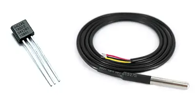
One of the advantages of the DS18B20 is that it is marketed both as a TO-92 integrated and in the form of a waterproof probe, allowing temperature measurements in liquids and gases.
The DS18B20 uses a communication bus called 1-Wire proprietary to Maxim Integrated, although we can use it without having to pay any fee (it is part of the device’s price).
The main advantage of the 1-Wire bus is that it needs a single conductor to perform communication (not counting the ground conductor). Devices can be powered directly by the data line, or through an additional line with a voltage of 3.0 to 5.5V.
Within the same 1-Wire bus, we can install as many sensors as we want. In addition, the 1-Wire bus allows the use of longer cables before communication deteriorates.
The DS18B20 also has an alarm system that allows recording upper and lower limits in the non-volatile memory of the DS18B20. The 1-Wire bus allows checking if any connected device has triggered an alarm.
The DS18B20 is a great sensor for temperature measurement, both in domestic and industrial environments. Its features allow the creation of networks with a large number of sensors to control, for example, the air conditioning or HVAC system of a commercial building.
Price
The DS18B20 is an inexpensive and excellent quality / price sensor. We can find it in its TO-92 integrated version for 0.45€, and for 1€ in the submersible version, searching in international sellers on eBay and AliExpress.
How does the DS18B20 work?
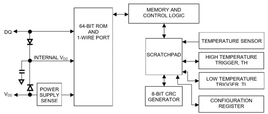
As we have said, internally the DS18B20 sensor is more complicated than we might initially think. It is composed of a processor with multiple modules, which are responsible for controlling communication, measuring temperature, and managing the alarm system.
One of the main advantages of DS18B20 is its 1-Wire communication bus that allows it to perform transmission using only a data cable. To do this, 1-Wire is based on a complex timing system in the signal, between the transmitting device and the receiver.
The communication signal used in 1-Wire, as well as its timings, are really long and complex. For more information, refer to the device’s Datasheet.
The main disadvantage of the 1-Wire system is that it requires complex code, which in turn results in a high processor load to check the status of the sensors. The total acquisition time for a measurement is 750ms.
The 1-Wire device allows all devices connected to the bus to be powered through the data line. For this, they have a capacitor that stores energy while the data line is HIGH. This mode is called “parasite mode”. If not using parasite mode, devices must be powered at a voltage between 3.0V and 5.5V.
In any case, the 1-Wire bus requires a 4k7 pull-up resistor between Vcc and Vq to function correctly.
In order to have multiple devices on a 1-Wire bus, each sensor has a ROM memory that is factory programmed with a 64-bit number. The first 8 bits correspond to the family (0x28 for the DS18B20). The next 48 bits are the unique serial number. The last 8 bits are a CRC code.

This means that potentially we could have 2^48 (more than 218 trillion) DS18B20 connected on the same 1-Wire network, as well as many devices from other families (2^28, about 268 million possible device families). In practical terms, this means infinite devices.
The resolution of the DS18B20 is configurable to 9, 10, 11, or 12 bits, with 12 bits being the default mode. This results in a temperature resolution of 0.5°C, 0.25°C, 0.125°C, or 0.0625°C, respectively.
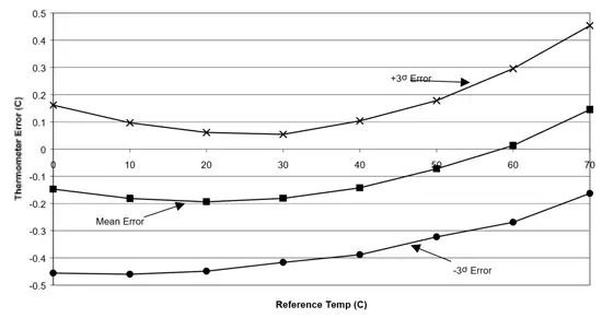
The fact that the DS18B20 has a default resolution of 0.0625ºC does not mean that this is its precision. However, the DS18B20 is considerably precise throughout the range of -10°C to +85°C. You can check the average deviations at 3 sigma in the following graph.
Assembly diagram
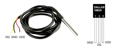
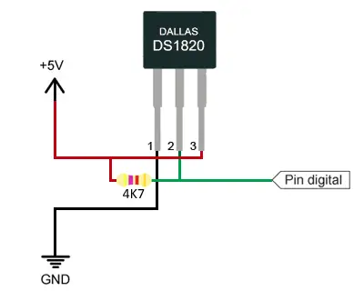
1-Wire devices have three terminals
- Vq, the data line
- Vdd, power line
- GND, ground line
The following image shows the position of these pins in both formats of the sensor, as integrated and as a waterproof probe.
We have mentioned that the 1-Wire bus requires a 4K7 pull-up resistor, and that we can power the sensor directly through the Vdd pin or use the “parasite” mode and power it with the data line itself.
Therefore, the simplest connection scheme is shown in the following image, where we can connect the sensor to any digital input of Arduino.
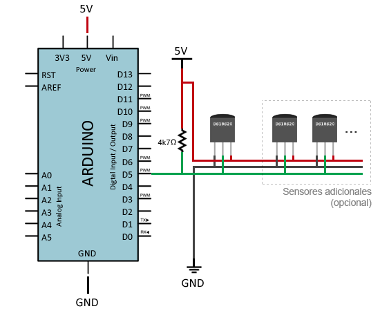
If we represent the same assembly, adding the arrangement that additional sensors would occupy (if needed), we can more clearly observe the structure of the 1-Wire bus.
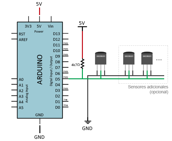
Finally, if we wanted to use the parasite mode, we simply have to connect Vdd of all devices to GND. This way, the sensors will take their power from the Vq data line. The assembly with the parasite mode would look like this.
Code examples
To read the temperatures of the DS18B20, we need to use the 1-Wire library and the Dallas Temperature library.
In the first example, we will read a single sensor located at digital pin 5.
#include <OneWire.h>
#include <DallasTemperature.h>

const int oneWirePin = 5;

OneWire oneWireBus(oneWirePin);
DallasTemperature sensor(&oneWireBus);

void setup() {
  Serial.begin(9600);
  sensor.begin();
}

void loop() {
    Serial.println("Reading temperatures: ");
  sensor.requestTemperatures();

  Serial.print("Temperature at sensor 0: ");
  Serial.print(sensor.getTempCByIndex(0));
  Serial.println(" ºC");

  delay(1000);
}
When using the getTempCByIndex function, the index is the sensor number. With this function, we can read more than one sensor installed on a bus, but we would have problems knowing which sensor is which index.
Therefore, in case of having multiple sensors, it is normal to access directly by the 64-bit device address. To know this address, we have to use the following sketch, which scans the 1-Wire bus and displays its address in hexadecimal format (grouped in 8 numbers of two digits).
#include <OneWire.h>

const int oneWirePin = 5;
OneWire oneWireBus(oneWirePin);

void setup(void) {
  Serial.begin(9600);
  discoverOneWireDevices();
}

void discoverOneWireDevices(void) {
  byte i;
  byte present = 0;
  byte data[12];
  byte addr[8];

  Serial.println("Searching for 1-Wire devices");
  while(oneWireBus.search(addr)) {
    Serial.println("Found 1-Wire device at address");
    for( i = 0; i < 8; i++) {
      Serial.print("0x");
      if (addr[i] < 16) {
        Serial.print('0');
      }
      Serial.print(addr[i], HEX);
      if (i < 7) {
        Serial.print(", ");
      }
    }
    if ( OneWire::crc8( addr, 7) != addr[7]) {
        Serial.print("Error in device, invalid CRC!\n");
        return;
    }
  }
  Serial.println("Search finished");
  oneWireBus.reset_search();
  return;
}

void loop(void) {
  // nothing to do here
}
Once we have the device addresses, we could perform the reading of multiple sensors on the same 1-Wire bus.
In the following example, we read two sensors for which we have already obtained their address, one inside and one outside a house, accessing through their address.
#include <OneWire.h>
#include <DallasTemperature.h>

const int oneWirePin = 5;

OneWire oneWireBus(oneWirePin);
DallasTemperature sensors(&oneWireBus);

DeviceAddress insideThermometer = { 0x28, 0x94, 0xE2, 0xDF, 0x02, 0x00, 0x00, 0xFE };
DeviceAddress outsideThermometer = { 0x28, 0x6B, 0xDF, 0xDF, 0x02, 0x00, 0x00, 0xC0 };

void setup(void)
{
  Serial.begin(9600);
  sensors.begin();
  sensors.setResolution(insideThermometer, 10);
  sensors.setResolution(outsideThermometer, 10);
}

void printTemperature(DeviceAddress deviceAddress)
{
  float tempC = sensors.getTempC(deviceAddress);
  if (tempC == -127.00) {
    Serial.print("Error getting temperature");
  } else {
    Serial.print(tempC);
  Serial.println(" ºC");
  }
}

void loop(void)
{

  Serial.println("Reading temperatures");
  sensors.requestTemperatures();

  Serial.print("Indoor Temperature: ");
  printTemperature(insideThermometer);
  Serial.print("Outdoor Temperature: ");
  printTemperature(outsideThermometer);
  Serial.println("-------");

  delay(2000);
}
Download the code
All the code from this post is available for download on Github. 
