
In this post, we are going to see how to make a PID constant lighting control with a simple LED and an LDR resistor.
We have talked a lot about PID on the blog in the control theory section. So we have seen the PID controller, how to tune a PID controller and how to implement a PID control in Arduino
Now it’s time to move on to a practical PID example. One of the most appropriate to start with is a lighting control, because the setup is very simple and we can easily visualize the result.
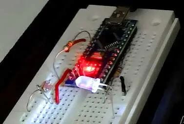
We only need to face an LED with an LDR resistor, although any other type of light emitter or sensor would work. In the setup, we face the LED with the LDR resistor as follows.
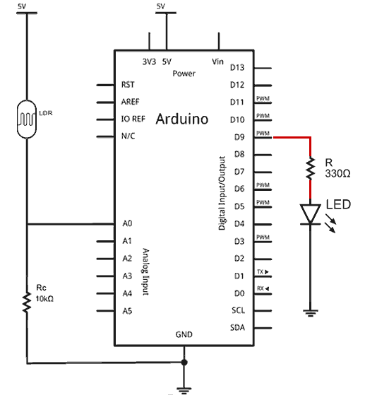
Now we want the LED to turn on and off in response to a disturbance, for example when we put our hand over the setup and partially block the ambient light.
The first thing we have to do is choose an appropriate setpoint, a point between fully lit, and totally (or quite dark). Otherwise, the PID will not have the capacity to “play” with the output.
For example, if you choose a setpoint lower than what you get with the LED off, the controller will not be able to go below that, no matter how much it turns off the LED. Similarly, if the light received by the LDR is much higher than that of the lit LED, it will have little effect, and the controller will be able to do little. It makes sense, doesn’t it?
So the first thing you should do is measure the value registered by the LDR with the LED off and fully lit, to determine an intermediate setpoint that is actually achievable for the controller.
Now it’s a matter of simply uploading the following code,
#include <PIDController.hpp>

const long A = 1000; //Resistance in darkness in KΩ
const int B = 15; //Light resistance (10 Lux) in KΩ
const int Rc = 10; //Calibration resistance in KΩ

const int PIN_LDR = A0;
const int PIN_LED = 9;

PID::PIDParameters < double > parameters(0.4, 6.0, 0.0001);
PID::PIDController < double > pidController(parameters);

void setup()
{
    Serial.begin(115200);
    pinMode(PIN_LED, OUTPUT);

    pidController.Input = analogRead(PIN_LDR);
    pidController.Setpoint = 350;

    pidController.TurnOn();
}

float readLDR()
{
    float mean = 0;
    for (auto i = 0; i < 100; i++) {
        auto V = (float) analogRead(PIN_LDR);
        mean += (V * A * 10) / (B * Rc * (1024 - V));
    }
    mean /= 100;
    return mean;
}

void loop()
{
    auto ilum = readLDR();
    Serial.println(ilum);

    pidController.Input = ilum;
    pidController.Update();

    analogWrite(PIN_LED, (int) pidController.Output);
}
Where we have used the PIDController library (since I made it, I’ll use it). Logically, you will have to adjust the K values and the setpoint for your setup. But, as a guide, they won’t be far from those in the example.
In the code, we are basically reading the LDR with a (simple) average of 100 measurements. This measurement is introduced as input to the PID controller, and its output as the PWM signal to apply to the LED.
Once we have everything ready, we turn on the setup. The result should be something like the following video, where when covering the setup it reacts by varying the LED intensity to maintain the lighting we have designated.
Furthermore, as we see, we can use the serial plotter of the Arduino IDE itself to graph the system response and adjust/verify its behavior.
This is a practical and real example of PID, which requires a very simple setup. This makes it very suitable for experiments with children, or in the field of education.
In future posts in the control theory section, we will see something a little more complex. A constant speed regulator for a DC motor with an encoder. See you next time!
