
What is a voltage transformer?
A transformer is an AC electrical machine that uses magnetic fields to adapt voltage and current levels between two circuits. We can use transformers to adapt the voltage of circuits to a manageable range for electronics and processors such as Arduino.
In addition to supplying electrical power, transformers can be used as instrumentation elements. In this case, we want to measure the voltage of the electrical grid. In most European countries, the electrical grid operates at 230VAC and 50Hz. These voltage values would immediately destroy an Arduino.
Other countries use other voltages and frequencies. You must adapt the values in this post to those available in your country.
At first, to measure an alternating voltage of 230VAC, we might be tempted to use a simple voltage divider with high value resistors (of the order of MO) along with a linear optocoupler with amplification.
However, using a transformer is a conventional and simple alternative, widely used even in commercial measurement systems. Unless you specifically know what you are doing, and have a reason, using a transformer should be the preferred option.
When using a transformer, we do not need an optocoupler since the transformer itself provides galvanic isolation. However, there is a magnetic coupling, so the secondary is still susceptible to large current peaks or overloads in the primary circuit. For this reason, we will incorporate a capacitor in the secondary.
The biggest disadvantage we will encounter when using a transformer is that it introduces a phase shift between the signal of the primary circuit and the secondary, which will make it difficult for us to determine the cosine of Phi (more information).
However, when making a consumption measurement, measuring the phase shift will always be one of the main problems, so, in any case, we would have to take measures to solve it.
On the other hand, the measured signal may have harmonic distortions due to the non-linearity of the transformer caused by the saturation of the magnetic core. The distortion will largely depend on the quality of the transformer used.
Transformers are devices widely used in all areas. They are used in electrical distribution to convert voltage and reduce losses during transport. They are also used in electrical and electronic devices in both the industrial and domestic fields to adapt grid voltages to the required voltage for the device.
In this post, we will use a 230VAC/15VAC transformer to measure voltage from a 230VAC, 50Hz electrical grid. Voltage measurement is a necessary component, for example, in projects to create a consumption monitor or an electrical supply quality analyzer.
Price
There are transformers of all price ranges and powers. Fortunately, since we only want to measure the voltage, a low-power transformer will be sufficient since we will not be consuming electricity.
We are looking for a mini transformer of 230VAC/12VAC or 230VAC/15VAC. They are inexpensive devices, and we should be able to find them for less than 1€.
Now comes the bad news, and it is that we will not easily find these mini transformers. Even if we find them, the shipping costs for buying a single unit will increase the price.
We have several alternatives:
The first option is to buy the mini transformer. We can find them for around 4-5€, by looking at international sellers on eBay or AliExpress.
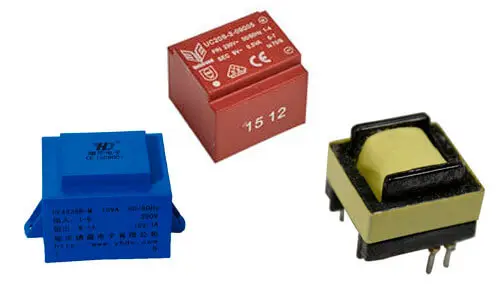
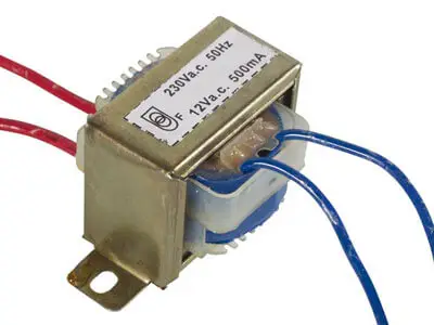
If you cannot find a mini transformer, another option is to use a “traditional” transformer of small size. We should be able to find them for around 5-6€, also from international sellers on eBay or AliExpress.
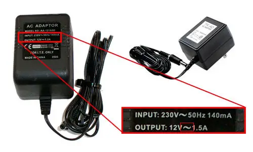
Another option is to use an AC-AC wall charger (be careful, the output is AC!). They are not easy to find, as most of them have AC output. Their price is somewhat higher, around 8-10€, but we will have the advantage of a compact and plastic-encapsulated device, where to measure all we have to do is plug it comfortably into the grid.
Finally, if possible, you can reuse the transformer from a device you disassemble. Sometimes it is even profitable to buy a driver (for example, for TFT or LED displays), which we can find for 1-2€, and use the mini transformer. The problem here will be finding a transformer that has the output voltage we want.
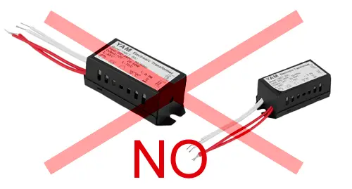
Rremember that we cannot use switched-mode power supplies or electronic AC-AC converters, such as those used for LED drivers. These converters use high-frequency oscillator circuits, so their output is completely distorted compared to the sinusoidal input voltage, so we cannot use them to make measurements in the grid voltage.
How does a transformer work?
Transformers are complex and widely studied machines. A detailed study is beyond the scope of this post, so we will limit ourselves to giving some guidelines to understand its operation.
If you are interested, there is extensive documentation on the web or feel free to ask any questions you need in the comments of this post.
In general, a transformer consists of two windings (that is, conductor coils) corresponding to the primary and secondary circuit. In most cases, the windings are wound around a ferromagnetic core.
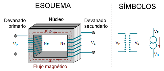
When we pass alternating current through the primary winding, it induces a magnetic flux inside it. This magnetic flux crosses (coils) the secondary winding, generating an induced voltage (or electromotive force).
The flux generated by the primary winding is proportional to its number of turns. In turn, the induced voltage in the secondary winding is also proportional to its number of turns. Therefore, the relationship between both voltages is proportional to the relationship between turns of both windings.
Assuming an ideal transformer with no losses, the electrical power is transmitted entirely between the primary and secondary winding. Therefore, it is easy to deduce that the relationship of intensities is inverse to the relationship between voltages and, therefore, to the relationship between the turns of the windings.
In summary,
This ability to change the relationship between voltages and intensities between the primary and secondary circuit simply by controlling the number of turns in the windings is what makes transformers so interesting.
Of course, real transformers have losses and limitations that distance them from their ideal behavior. However, in general, transformers are machines with high efficiencies, typically 95-98%.
The main losses that deviate the transformer from its ideal behavior are losses in the copper due to Joule effect, losses due to induced parasitic currents in the core (Foucault currents), losses due to magnetic field dispersion, and losses due to hysteresis in the core material.
The reason why transformers have a ferromagnetic core is precisely to reduce losses due to dispersion. It provides a path of low magnetic resistance (reluctance) for the magnetic flux to pass from one winding to another.
For the same reason, and although in the diagrams the windings are usually represented in each of the columns of the core, other arrangements are generally adopted, for example, in which both windings are wound in the same column and the rest of the core allows a return path of the magnetic flux.
To reduce losses due to induced currents in the magnetic core, it is usually formed by several insulated sheets, so that the path traveled by the currents is limited, and therefore the heat generated.
Transformers preserve the frequency of the alternating current on both sides. However, since the coils that make up the transformer are reactive loads, the transformer may have an angular phase shift between the primary and secondary circuit.
Finally, it should be noted that transformers generate signal distortions due to the non-linearity of the core material, especially in the saturation zones, resulting in the introduction of harmonic components in the output.
Assembly diagram
To carry out this assembly, we will have to solve two main problems,
- Voltage range adaptation
- Positive and negative voltages
Grid voltages are dangerous for people. Perform the assembly with special care and only if you feel comfortable handling electricity.
Voltage range adaptation
We must adapt the range of voltages to a value acceptable for electronics. In Europe, most countries have a grid voltage of 230V/400V 50Hz (single-phase/three-phase) with a 10% tolerance, so the possible voltage is 214-247V.
On the other hand, we must remember that the grid voltage is measured in Vrms. Let’s briefly remember the peak voltage and peak-to-peak equations.
Therefore, the peak voltage could reach 247*1.414 = 350V, and the peak-to-peak voltage 700V.
We are going to use a transformer with an output between 12VAC. In this case, the peak voltage at the output will be 18.66V and the peak-to-peak voltage 37.33V. In the case of using a 15VAC transformer, the peak voltage will be 23.33V, and the peak-to-peak voltage will be 46.66V.
These voltage values are high, but acceptable for a simple voltage divider like the FZ0430, which allows measuring voltages of up to 25V.
Positive and negative voltages
The other problem we have to solve is that the voltage in the transformer’s secondary is also alternating. But as we know, the analog inputs of most Arduinos can only measure positive voltages.
To measure the voltages at the output of the transformer, we have several options, from worst to best.
Rectify the signal using a diode bridge and measure the waveform as positive values. Not recommended since we lose the information on whether we are in the positive or negative half-period, also because we will have the voltage drop of the diode, and, even worse, the diode does not conduct below a certain voltage so the signal will be distorted at the zero crossings.
Add a DC offset using two resistors and a capacitor that provide a midpoint between GND and Vcc. Much better if we also add an operational amplifier as a voltage follower.
Add an ADC with differential input, which allows measurements of positive and negative voltages, such as the ADS1015 or the ADS1115. This is the option we are going to use.
The ADS1015 has a lower resolution of 12 bits but a higher sampling frequency. If you do not need the precision of the ADS1115, the ADS1015 is a simpler option.
Electrical connection
We have already presented all the necessary components to measure the grid voltage at 230VAC simply (now we will see how this choice is not casual).
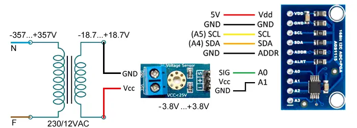
By on one side, we have a 230VAC to 12VAC transformer. Also a voltage divider like the FZ0430 and, finally, a 12-bit ADS1115 ADC.
By connecting these devices, we can measure the grid voltage, which we have calculated to be ±357V, and ±18.7V after the transformer. After the FZ0430, the voltage is ±3.8V, which is perfect for the differential mode of the ADS1115 configured in range ± 4.096V. The measurement will have a precision of 12mV.
Using a 15VAC transformer, the voltage after the transformer would be ±23.33V, still acceptable by the FZ0430, and the output would be ±4.66V, acceptable by the ADS1115 in range ±6.144V, although in this case we would have a slightly lower value of 15mV.
The connection, seen from Arduino, is only the power supply of the ADS1115 module, as we saw in the post on the ADS1115.
If you do not want to use the FZ0430 and the ADS1115 and prefer to add an offset, the scheme would be as follows.
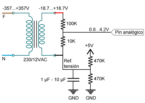
Where we have used a voltage divider with a ratio of 1:11 so that the peak-to-peak voltage of 37.4V becomes 3.4V, and we use a DC offset point of 2.5V, the final range is 0.8V to 4.2V, within the range of the analog inputs of Arduino.
In the case of using a 12VAC transformer, the range would be 0.4V to 4.6V, also within the range of the analog inputs of Arduino.
Code examples
Assembly with FZ0430 and ADS1115
If you have used the assembly with FZ0430 and ADS1115, the necessary code is similar to what we saw in the post on the ADS1115. You will need the Adafruit library for the ADS1115.
#include <Wire.h>
#include <Adafruit_ADS1015.h>

Adafruit_ADS1115 ads;

// const float multiplier = 0.1875F; // 15V transformer
const float multiplier = 0.1255F; // 12V transformer

void setup()
{
  Serial.begin(115200);

  // ads.setGain(GAIN_TWOTHIRDS);  // 15V transformer
  ads.setGain(GAIN_ONE);       // 12V transformer
  ads.begin();
}

void loop()
{
  while(1)
  {
    Serial.print(ads.readADC_Differential_0_1() * multiplier);
  }
}However, the sampling time of the library is conditioned by an 8ms wait, resulting in 128 samples/s. To achieve higher reading rates, you can replace the waits of delay(m_conversionDelay); with delayMicroseconds(800); and #define ADS1015_REG_CONFIG_DR_1600SPS (0x0080) with #define ADS1015_REG_CONFIG_DR_1600SPS (0x00E0).
Assembly with resistors and midpoint
In this case, the example is very simple, we only have to make the measurement using an analog input.
const int sensorPin = A0;
int sensorValue;
float value;

void setup()
{
  Serial.begin(9600);
}

void loop()
{
 sensorValue = analogRead(sensorPin);
 value = fmap(sensorValue, 0, 1023, -426.2080, +426.2080);

 delay(1);
}

// scale change between floats
float fmap(float x, float in_min, float in_max, float out_min, float out_max)
{
 return (x - in_min) * (out_max - out_min) / (in_max - in_min) + out_min;
}Download the code
All the code in this post is available for download on Github.

