In this post, we will learn how to measure the light level, both indoors and outdoors, with the help of Arduino and an LDR photoresistor (GL55 family or similar), using the analog inputs of Arduino.
What is an LDR photoresistor?
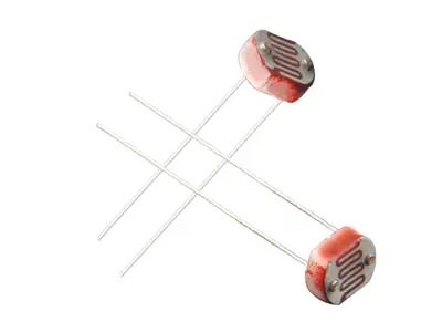
A photoresistor, or LDR (light-dependent resistor), is a device whose resistance varies depending on the received light. We can use this variation to measure, through the analog inputs, an estimation of the light level.
A photoresistor is made up of a semiconductor, typically cadmium sulfide CdS. When light shines on it, some of the photons are absorbed, causing electrons to move to the conduction band and, therefore, decreasing the component’s resistance.
Therefore, a photoresistor decreases its resistance as the light on it increases. Typical values range from 1 MOhm in total darkness to 50-100 Ohm in bright light.
On the other hand, the resistance variation is relatively slow, from 20 to 100 ms depending on the model. This slowness makes it impossible to record rapid variations, such as those produced in artificial light sources powered by alternating current. This behavior can be beneficial, as it gives the sensor great stability.
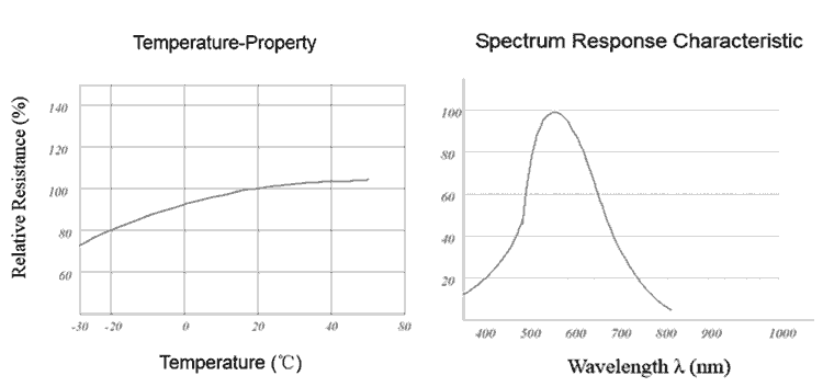
Finally, photoresistors are not suitable for providing a measurement of illuminance, that is, for serving as a lux meter. This is due to their low precision, their strong dependence on temperature, and especially because their spectral distribution is not suitable for illuminance measurement.
Therefore, an LDR is a sensor that is suitable for providing quantitative measurements of the light level, both indoors and outdoors, and reacting, for example, by turning on a light, raising a blind, or orienting a robot.
To measure the amount of lux with Arduino, you will need a lux meter such as the BH1750, as seen in the post Measuring lux with Arduino and the BH1750 lux meter
Price
Photoresistors are really cheap devices. We can find 20 LDR sensors for €1 from international sellers on Ebay, including shipping costs.
How does an LDR photoresistor work?
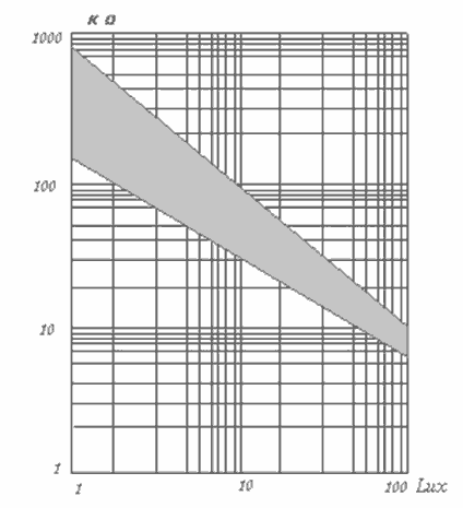
Mathematically, the relationship between illuminance and the resistance of an LDR follows a potential function.
Where R0 is the resistance at an intensity I0, both known.
The constant gamma is the slope of the logarithmic graph, or the resistance loss per decade. Its value is typically 0.5 to 0.8.
For this reason, graphs relating both values are often represented on logarithmic scales for both axes. Under this representation, the relationship is shown as a linear graph.
These values can be obtained from the component’s datasheet. For example, for the GL55 family of photoresistors, they are as follows:
| Model | Spectral Peak (nm) | Bright Light Resistance (KΩ) | Dark Resistance (KΩ) | gamma | Response Time (ms) |
|---|---|---|---|---|---|
| GL5516 | 540 | 5-10 | 500 | 0.5 | 30 |
| GL5528 | 540 | 10-20 | 1000 | 0.6 | 25 |
| GL5537-1 | 540 | 20-30 | 2000 | 0.6 | 25 |
| GL5537-2 | 540 | 30-50 | 3000 | 0.7 | 25 |
| GL5539 | 540 | 50-100 | 5000 | 0.8 | 25 |
| GL5549 | 540 | 100-200 | 10000 | 0.9 | 25 |
However, there will always be small variations between devices, even within the same family, due to the manufacturing of the component.
The potential behavior means that these small differences result in large variations in the measurement, so it is not generally possible to use these values in an absolute way without a calibration process.
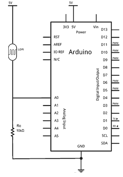
Electrical schematic
The electrical schematic would be as follows.
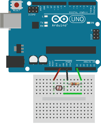
Assembly
On the other hand, the electrical assembly on a breadboard would look like this.
Code Examples
Here are some code examples. In the following, we use the digital inputs to flash the LED integrated on the board while the LDR receives sufficient light.
const int LEDPin = 13;
const int LDRPin = 2;

void setup()
{
pinMode(LEDPin, OUTPUT);
pinMode(LDRPin, INPUT);
}

void loop()
{
  int value = digitalRead(LDRPin);
  if (value == HIGH)
  {
    digitalWrite(LEDPin, HIGH);
    delay(50);
    digitalWrite(LEDPin, LOW);
    delay(50);
  }
}
The following example uses an analog input to activate the integrated LED on the board if it exceeds a certain threshold.
const int LEDPin = 13;
const int LDRPin = A0;
const int threshold = 100;

void setup() {
  pinMode(LEDPin, OUTPUT);
  pinMode(LDRPin, INPUT);
}

void loop() {
  int input = analogRead(LDRPin);
  if (input > threshold) {
    digitalWrite(LEDPin, HIGH);
  }
  else {
    digitalWrite(LEDPin, LOW);
  }
}
The following code provides a reading of the received light level. Note that the calculations are done with integer arithmetic, avoiding the use of floating-point numbers, as they greatly slow down the code execution.
const long A = 1000;     // Dark resistance in KΩ
const int B = 15;        // Light resistance (10 Lux) in KΩ
const int Rc = 10;       // Calibration resistance in KΩ
const int LDRPin = A0;   // LDR Pin

int V;
int ilum;

void setup()
{
   Serial.begin(115200);
}

void loop()
{
   V = analogRead(LDRPin);

   //ilum = ((long)(1024-V)*A*10)/((long)B*Rc*V);  //use if LDR between GND and A0
   ilum = ((long)V*A*10)/((long)B*Rc*(1024-V));    //use if LDR between A0 and Vcc (as in the previous schematic)

   Serial.println(ilum);
   delay(1000);
}
Download the code
All the code from this post is available for download on Github. 
