What is the PCF8574?
The PCF8574 is an I2C bus digital input/output expander manufactured by Philips. It can be connected to a processor like Arduino to control more devices using fewer pins.
The PCF8574 incorporates 8 quasi-directional pins based on CMOS outputs in an open drain configuration. This means that they can be used as both inputs and outputs, with certain considerations that we will see in the connection and assembly section.
The maximum current that each pin can supply, when acting as an output, is 25mA when acting as a sink (current flows towards the PCF8574) and 300µA when acting as a source (current flows from the PCF8574). Therefore, the normal configuration is as a sink.
All outputs have Latches, meaning they maintain their state by themselves without the need for actions from Arduino. We only need to act when we want to modify the state of one of the outputs.
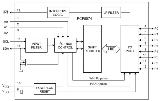
Communication is done through the I2C bus, so it is easy to obtain the measured data. It has 3 address pins, which gives 8 possible connections to the same I2C bus. Therefore, it is possible to control 64 devices using only 2 pins.
It also has an interrupt line (INT) that can be used to detect a change in one of its pins. Connected to an Arduino interrupt pin, we can detect the reception of data without the need to constantly monitor the state of the inputs.
The PCF8574 operating voltage is between 2.5V and 6V. On the other hand, its standby consumption is very low, less than 10 µA.
We can use the PCF8574 to expand the number of available digital inputs and outputs, and control 8 devices (or up to 64 if we use multiple modules) with only 2 pins. This is especially useful in Arduino models with fewer pins, such as the Attiny85 used in Digispark boards.
Price
We can find modules with PCF8574 ready to connect to Arduino for €1.30, by searching international sellers on eBay and AliExpress.
If we acquire the integrated chip alone, without the module, we can find them for €0.30.
Assembly diagram
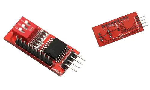
The connection of the modules that integrate the PCF8574 is quite simple, we simply power the module from Arduino using GND and 5V and connect the SDA and SCL pins of Arduino to the corresponding pins of the sensor.
If we are using the integrated chip directly, the connection scheme would be as follows.
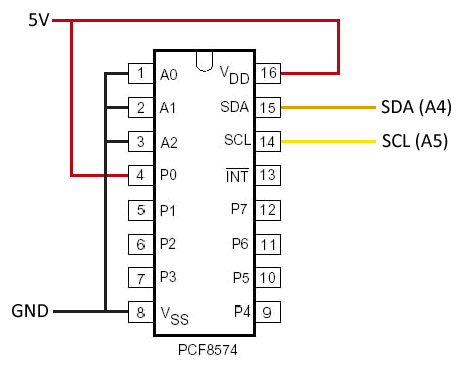
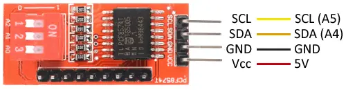
In both cases, the connection seen from Arduino would be the same, according to the following diagram
On Arduino Uno, Nano and Mini Pro, SDA is pin A4 and SCK is pin A5. For other Arduino models, consult the pinout scheme accordingly.
Connecting the loads to each of the 8 pins is also not difficult, if we take into account certain considerations. As we have said, each quasi-bidirectional pin has an open drain configuration.
In a simplified summary, within each pin we have a CMOS transistor along with a weak pull-up resistor, which imposes a current intensity of 100 uA when the transistor is activated.
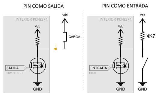
When the pin acts as an output, the PCF8574 acts as a current sink, meaning the current flows inwards, and the logic of the outputs is inverted.
- When the output is LOW, the voltage seen by the load is Vdd, and therefore no current flows.
- When the output is HIGH, the load is connected to Gnd, and up to 25 mA can pass through.
When the PCF8574 pin acts as an input, we must always set it to HIGH. Under these conditions, the internal pull-up resistor limits the leakage current to 100 uA. When connecting a load, we must use a pull-up resistor, just as we do whenever we read a button.
- When the external load is closed, the voltage on the pin goes to GND.
- When the external load is open, the voltage on the pin goes to Vdd.
Code examples
Without library
The following code shows the use of the PCF8574 as an output. In the example, we turn on and off each of the pins in a loop. Note that the channel signal is sent inverted, because the PCF8574 acts as a current sink and the pin is active when the output is LOW.
#include <Wire.h>

const int pcfAddress = 0x38;

void setup()
{
  Wire.begin();
  Serial.begin(9600);
}

void loop()
{
  for (short channel = 0; channel < 8; channel++)
  {
    // Write data to 'channel' pin
    Wire.beginTransmission(pcfAddress);
    Wire.write(~(1 << channel));
    Wire.endTransmission();

    // Read data from pin
    delay(500);
  }
}
The following code shows the use of the PCF8574 as an input. In the example, we progressively read each of the pins, and display its value on the serial port.
#include <Wire.h>

const int pcfAddress = 0x38;

void setup()
{
  Wire.begin();
  Serial.begin(9600);
}

void loop()
{
  short channel = 1;
  byte value = 0;

  // Read data from 'channel' pin
  Wire.requestFrom(pcfAddress, 1 << channel);
  if (Wire.available())
  {
    value = Wire.read();
  }
  Wire.endTransmission();

  // Display the value on the serial port
  Serial.println(value);
}
With library
Alternatively, we can use a library such as the one developed by SkyWood available at https://github.com/skywodd/pcf8574_arduino_library. The library provides example codes to illustrate its use. However, here is a summarized example that shows its use.
#include <Wire.h>
#include "PCF8574.h"

PCF8574 expander;

void setup()
{
  Serial.begin(9600);

  expander.begin(0x20);

  /* Setup some PCF8574 pins for demo */
  expander.pinMode(0, OUTPUT);
  expander.pinMode(1, OUTPUT);
  expander.pinMode(2, OUTPUT);
  expander.pinMode(3, INPUT_PULLUP);

  /* Blink hardware LED for debug */
  digitalWrite(13, HIGH);

  /* Toggle PCF8574 output 0 for demo */
  expander.toggle();

  /* Blink hardware LED for debug */
  digitalWrite(13, LOW);
}

void loop()
{
}
Download the code
All the code from this post is available for download on Github. 
