What is a CD74HC4067 multiplexer?
Multiplexers and demultiplexers are devices that allow us to control a greater number of devices with a smaller number of inputs or outputs. We can use these devices to expand the number of inputs and outputs of a processor such as Arduino.
A multiplexer (or mux) allows us to direct multiple signals to a single input. The reverse device is called a demultiplexer (or demux) and allows us to direct a single signal to multiple outputs.
The CD74HC4067 is a 16-channel bidirectional Multiplexer/Demultiplexer. We can consider it as a digitally controlled switch, which connects the common pin with one of the available channels.
This allows us to write to or read from 16 devices with just 5 pins. 4 of them control the device we want to read. The remaining pin collects the signal read or written on the selected channel.
The CD74HC4067 works with digital and analog signals both as input and output. For this reason, these types of devices are called input and output expanders (I/O expanders).
The CD74HC4067 can also be used in communication devices such as the serial port, I2C bus, or SPI bus. For example, we can connect the TX pin of the UART to send information to multiple devices. However, for complete communication, we will need more than one CD74HC4067, one for each pin involved in the communication.
The maximum current it can provide is 20 mA, limited, but it is not a big problem since it is similar to the maximum current that an Arduino pin can provide. For higher currents, an amplification stage using a transistor, or output by relay, will be necessary.
The supply voltage of the CD74HC4067 is between 2V to 6V. In any case, the signal voltages of the devices cannot exceed the Vcc voltage.
Price
CD74HC4067 multiplexers are inexpensive devices. We can find them for €0.80 from international sellers on eBay or AliExpress.
Assembly diagram
The connection is simple. On one hand, we power the CD74HC4067 by connecting Vcc and Gnd respectively to 5V and Gnd on Arduino. We also connect the chip EN to 5V, to activate the CD74HC4067.
On the other hand, we connect the S0, S1, S2, and S3 pins, which control the active channel, to 4 digital outputs of Arduino. Finally, we connect the signal pin to an input or output of Arduino. In the diagram, we will use pin A0, but it could be any other analog or digital pin.
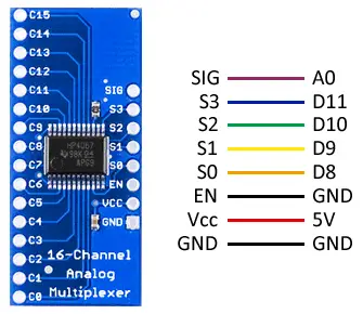
The connection, seen from Arduino, would be as follows, where we have used pin A0 again, but we could use any other pin.
Code examples
CD74HC4067 as output
In the first example, we show the use of the CD74HC4067 to add outputs. The following code progressively turns on and off the 16 channels. To do this, we change the direction pins, and use a digital output of Arduino to turn on and off the signal pin.
const int muxSIG = A0;
const int muxS0 = 8;
const int muxS1 = 9;
const int muxS2 = 10;
const int muxS3 = 11;

int SetMuxChannel(byte channel)
{
  digitalWrite(muxS0, bitRead(channel, 0));
  digitalWrite(muxS1, bitRead(channel, 1));
  digitalWrite(muxS2, bitRead(channel, 2));
  digitalWrite(muxS3, bitRead(channel, 3));
}

void setup()
{
  pinMode(muxSIG, OUTPUT);
  pinMode(muxS0, OUTPUT);
  pinMode(muxS1, OUTPUT);
  pinMode(muxS2, OUTPUT);
  pinMode(muxS3, OUTPUT);
}

void loop()
{
  for (byte i = 0; i < 16; i++)
  {
    SetMuxChannel(i);
    digitalWrite(muxSIG, HIGH);
    delay(200);
    digitalWrite(muxSIG, LOW);
    delay(200);
  }
}
CD74HC4067 as input
The following example shows the reading of values using the CD74HC4067. The following code sequentially performs the analog reading of pin A0, and shows the reading through the serial port. Just like in the previous code, we change the direction pins, but now we use the analog reading of the signal pin.
const int muxSIG = A0;
const int muxS0 = 8;
const int muxS1 = 9;
const int muxS2 = 10;
const int muxS3 = 11;

int SetMuxChannel(byte channel)
{
  digitalWrite(muxS0, bitRead(channel, 0));
  digitalWrite(muxS1, bitRead(channel, 1));
  digitalWrite(muxS2, bitRead(channel, 2));
  digitalWrite(muxS3, bitRead(channel, 3));
}

void setup()
{
  Serial.begin(9600);
  pinMode(muxS0, OUTPUT);
  pinMode(muxS1, OUTPUT);
  pinMode(muxS2, OUTPUT);
  pinMode(muxS3, OUTPUT);
}

void loop()
{
  for (byte i = 0; i < 16; i++)
  {
    SetMuxChannel(i);
    byte muxValue = analogRead(muxSIG);

    Serial.print(muxValue);
    Serial.print("\t");
  }
  Serial.println();
  delay(1000);
}
Download the code
All the code from this post is available for download on Github. 
