We continue with the 3D design and printing section, looking at the operations available in CAD software.
Throughout the section, we have seen that there are different ways to represent objects in 3D, as well as different types of 3D design software. We already said that, although it’s not the only type, in many cases we would use CAD software.
So in the previous post, we spent some time looking at the basics of CAD software. In this post, it’s time to delve a little deeper and see the 3D operations available in CAD software.
As usual, we won’t stick to any particular CAD software. Because we don’t want to learn a CAD software, we want to learn how to draw.
This way, we can quickly switch from one CAD software to another, and it will only be a matter of “where is this icon” or “how do I do this here.” But we will know exactly what we want and can do.
Therefore, let’s look at the 3D design operations available in CAD software. And indeed, these operations are the same in different CAD programs because they are “given” by the mathematics they are based on.
So it’s good for you to know them, know what options they have, when and where we can use them, and learn when it’s more convenient to use one or the other.
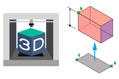
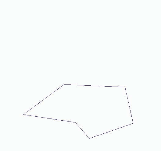
Extrusion
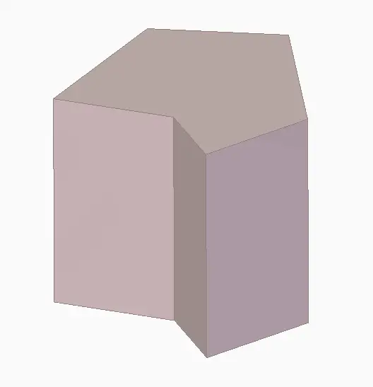
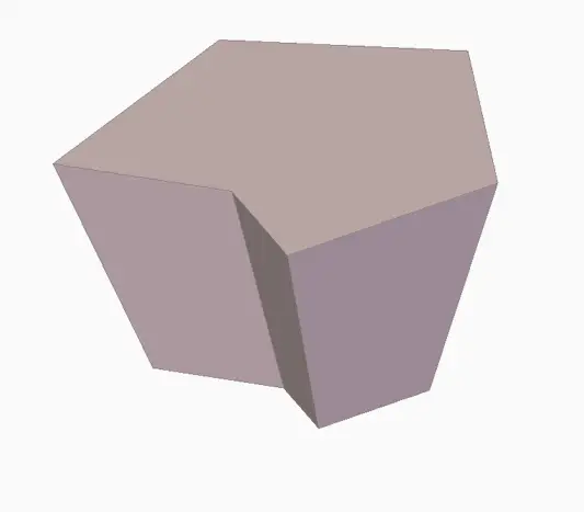
Probably the most basic and common operation in any CAD software. Extrusion generates a volume contained by a closed shape as it moves a distance along the normal (perpendicular) to the plane containing the shape.
Extrusion is, in many cases, the 3D operation we will use the most. In its additive form, it allows generating shapes from simple forms, like prisms and cylinders, to more complex solids (depending on the shape we use). In its subtractive version, an extrusion can be called holes or hollows.
A common option is to add an angle to the extruded faces. This angle is traditionally called a ‘draft angle’, because it makes sense in mold making to facilitate part removal. However, it can also be used to generate, for example, truncated conical or trapezoidal solids.
Revolution
Another of the most basic operations in any CAD program is revolution. Revolution generates a volume by rotating a closed surface around an axis.
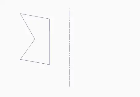
The rotation can be complete (360º) or with an open angle, in which case the generating surface forms a “cap” at both ends of the volume.
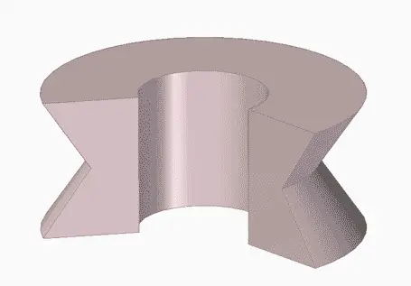
Revolution is an indispensable operation in the very common case of having to work with revolution shapes like shafts.
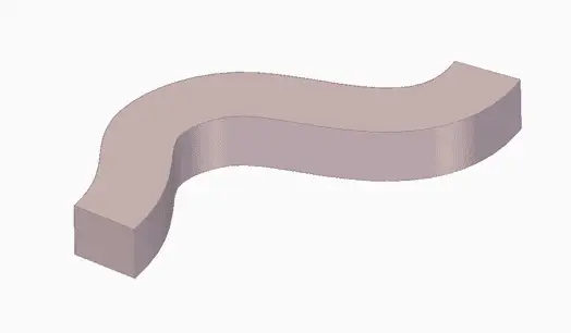
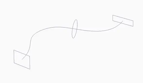
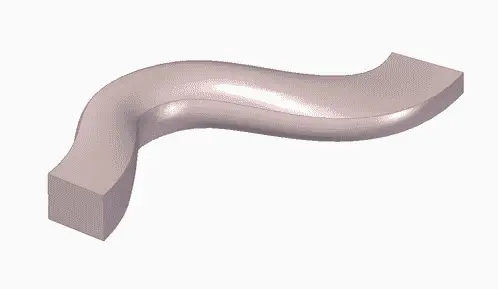
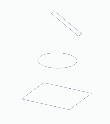
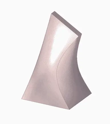
Sweep
The sweep operation is one of the most powerful available in CAD software. In fact, extrusion and revolution are special cases of it.
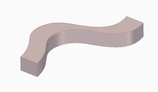
As the name suggests, the operation generates a volume by moving (sweeping) a closed shape along any path.
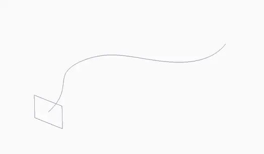
Among the typical options is how the orientation of the shape is maintained relative to the curve. The most common options (there are variations) are that the shape follows the tangent of the guide curve, or that it maintains the original orientation.
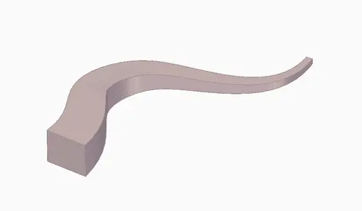
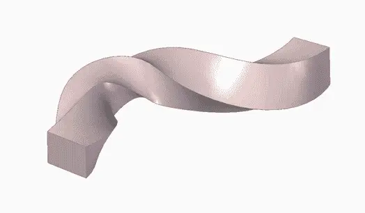
Frequently, it is also possible as an option to vary the rotation and/or scale of the shape along the displacement along the guide curve, allowing the generation of a wide variety of shapes (helices, drill bits, “hairs”, etc.)
It is also possible to add more than one shape (profile) along the guide curve. In this case, the generated volume makes a transition between the different provided profiles.
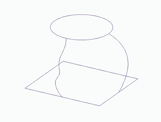
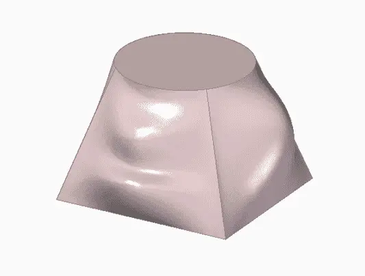
Loft
The loft operation is another of the most “powerful” operations for generating solids. It is generated by the transition between two or more closed shapes (profiles).
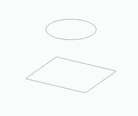
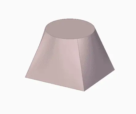
As mentioned, it is possible to indicate more than two profiles. In this case, the generated solid makes the transition between the indicated shapes.
Finally, it is possible to add one or more rails to add more detail to the transition between profiles.
Draft Face
Draft face is a very simple operation that, as the name suggests, rotates the indicated faces relative to another.
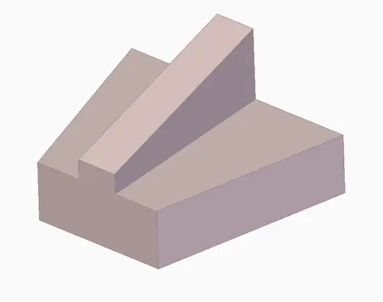
Normally, the draft face operation is associated with mold making, where it is necessary to create an angle to facilitate part removal from the mold.
Therefore, it is sometimes forgotten, but it can make our lives easier whenever we have to work with parts with inclined faces.
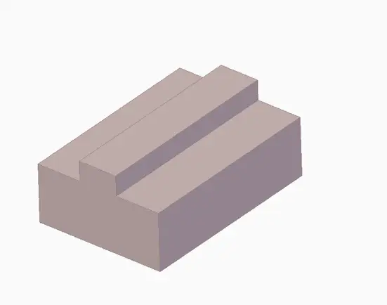
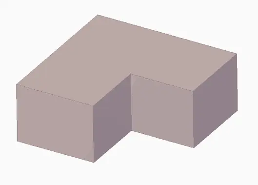
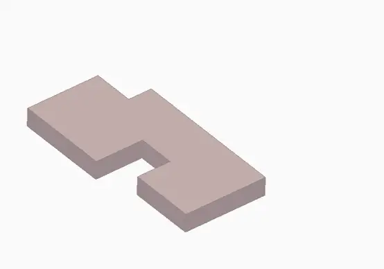
Thicken
The thicken operation is another one often forgotten in CAD software. Its operation is simple and consists of removing one or more faces of a solid, giving thickness to the remaining ones.
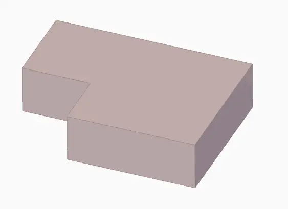
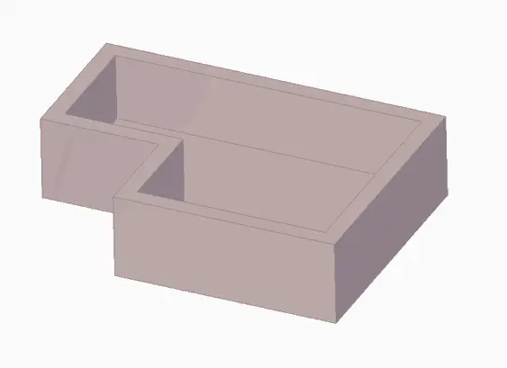
The thicken operation is normally associated with creating “boxes” or shells. But, as with draft face, remember that it’s not only for that, and it’s a good way to draw relatively “simple” shapes quickly, avoiding a lot of 2D sketches.

In particular, it is a good tool for easily drawing even simple shapes like ‘L’s, ‘U’s. Furthermore, it facilitates later modification because we only have to modify the original solid, instead of having to deal with a bunch of 2D curves.
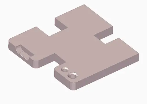
Round (Fillet)
The round (or fillet) operation is one of the most common in any CAD software. As the name suggests, it converts one or more edges into a rounded fillet.
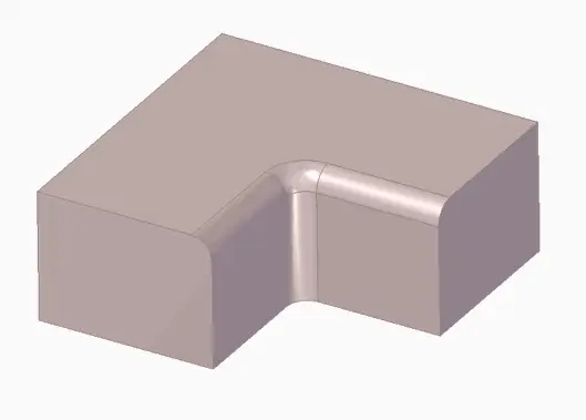
Among the usual options is the treatment of corners and points where several edges converge, or the behavior with neighboring faces and fillets.
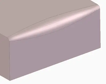
In more advanced versions, the rounding function allows varying the radius at different points of the edge, and the generated surface adapts.
The rounding function is a quick way to make our models look much more “attractive and complex.” For this reason, it is sometimes overused in tutorials and examples.
Despite this, in real life it is an almost indispensable function. It allows removing stress concentrators and facilitating part manufacturing. However, in many cases, the rounding function will be performed at the end of the design process.
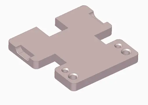
Chamfer
The “sister” function of rounding, adding a chamfer to an edge. The options and functionalities are similar to those available for fillets.

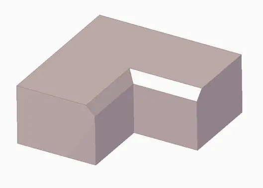
The chamfer function is useful not only for breaking edges but also for generating countersinks, designing couplings between parts, working with ribs, and removing stress concentrators.
Mirror
The mirror operation allows creating “mirror” copies of parts of a part, of operations, or of entire parts.
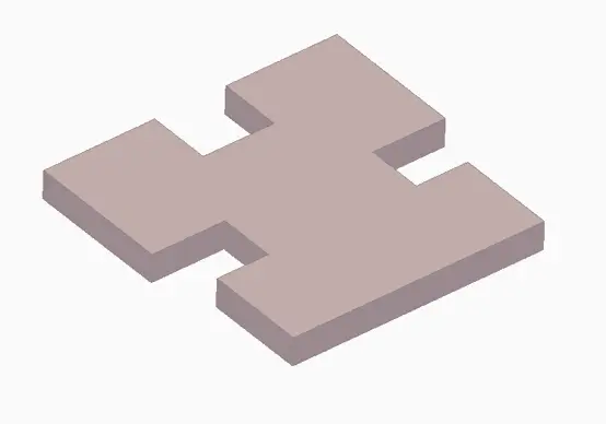
Many of the objects we work with have planes of symmetry. The mirror operation allows us to avoid a lot of unnecessary work by drawing only one part of the part instead of the whole.
Furthermore, it facilitates the modification and maintenance of our designs and avoids errors by, for example, moving a hole and leaving its symmetric counterpart in another part of the part.
Creating symmetries is an indispensable tool to avoid unnecessary work and facilitate the modification and maintenance of our designs.
Pattern
Another common operation in any CAD software, and essential to avoid repetitive work, is the ability to create repetitions (propagations, patterns…) of operations or parts of our part.
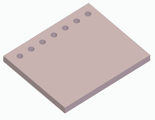
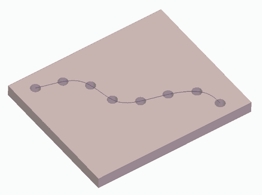
These repetitions can be one-dimensional, either in a straight line or along a guide curve.
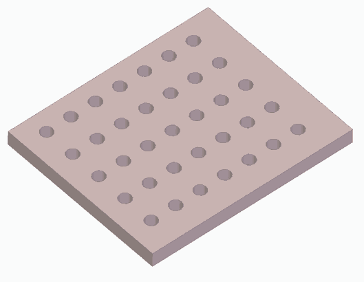
Two-dimensional operations are also frequent, such as rectangular patterns (only the outline, or filled).
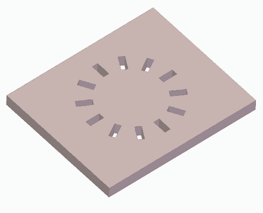
Finally, circular patterns are also common, either reorienting the operation or keeping it fixed.
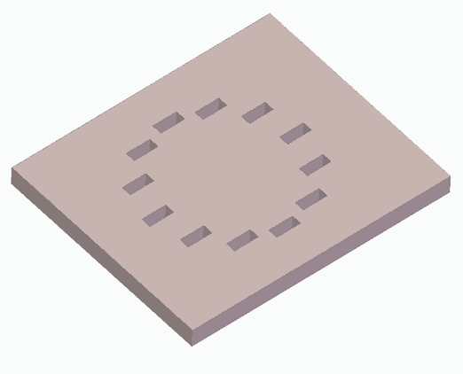
These are the most frequent cases of repetitions, although some software may offer additional patterns. The option to exclude one or more instances from the propagation is also frequent.
Conclusion
We have seen the CAD operations available that are common to most software. Although some software may not have all of them implemented or have them with more limited options.
Knowing the operations is essential to be able to tackle a 3D design. Before we start drawing, it is advisable (more like necessary) to analyze the geometry and imagine what is the fastest and most efficient way to draw it.
On the other hand, my particular advice is that in the design process you move to 3D as soon as possible, reducing the number of 2D sketches and shapes you have to draw. In the long run, you will save work, errors, and your designs will be easier to maintain and modify.
Likewise, logically, use the simplest operation that fulfills your purpose. That is, if you can use an extrusion instead of a sweep, and it is not foreseeable that you will need it in the future, choose the simplest one (KISS philosophy, “Keep It Simple”).
Of course, analyze the option of using symmetries and patterns to be more efficient. And remember that certain tools, like thicken or draft face, are often forgotten and can save us work.
As a final piece of advice, it’s good that, at least once, you spend some time drawing each of these operations in the software you usually use. This way, you will lose the “fear” of them when you need them.
And that’s it regarding 3D basics. In the rest of the section, we will “assume” that you already know how to draw (…congratulations?), so we move on to aspects specific to the printing process and 3D design for 3D printing. See you soon!