In the world of programming, when you learn a new language, tradition dictates that the first thing you should do is write a program that says “Hello World” on the screen.
In the world of electronics and Arduino, our “Hello World” is not text on a screen. It’s something much more physical: making a light blink.
Today we are going to write our first Sketch (that’s what Arduino programs are called). And the best part is that you don’t need to connect anything yet. We are going to use a small LED that already comes on the Arduino board itself.
Most Arduino boards (UNO, Nano, Mega) have a built-in test LED connected to Pin 13. In the code, it’s called LED_BUILTIN.
The Anatomy of a Sketch
Open your Arduino IDE. If you create a new file (File > New), you’ll see it’s not empty. Arduino always gives us a basic skeleton.
This skeleton has two fundamental parts that must always exist. They are the heart of any Arduino program:
void setup() {
  // put your setup code here, to run once:
}

void loop() {
  // put your main code here, to run repeatedly:
}
Let’s understand them with an analogy from your daily life:
The setup() Zone
This function runs only once, right when you turn on the Arduino or press the reset button.
It’s the moment to “pack your backpack before going to school”. Here we set things up: we say which pins we are going to use, start communications, etc.
Once done, it’s not looked at again (until you reset the board).
The loop() Zone
As its name suggests (loop means cycle), the code we write here will repeat infinitely, over and over, as fast as possible, until we disconnect the power.
It’s your daily routine: wake up, eat, sleep… and start over.
This configuration, a setup function and a continuously executing loop, is common in microcontroller programming.
It’s the only one allowed by the standard Arduino IDE (other configurations are possible using other IDEs, but they are not common).
Our First Program
To test the operation of our setup, we are going to use one of the examples included in the Arduino IDE.
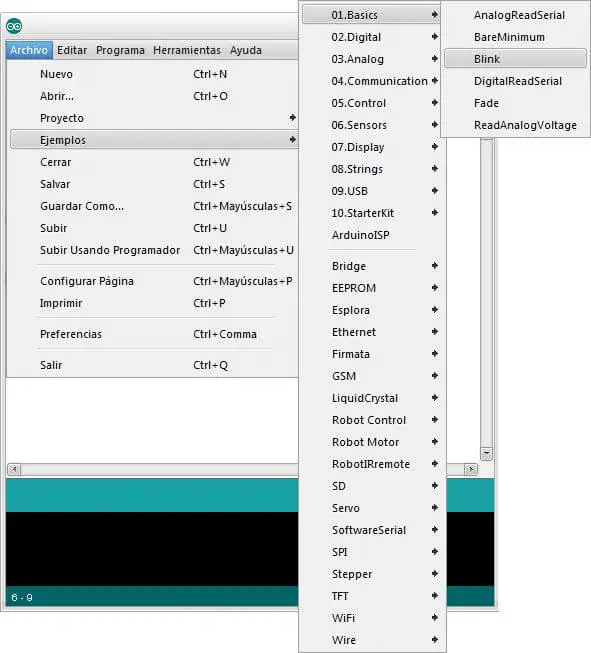
We select the example Basics / Blink, and a code similar to the following will appear.
const int pinLED= 13;    //assign variable led as 13

void setup()
{
  pinMode(pinLED, OUTPUT);     //define pin 13 as output
}

void loop() {
  digitalWrite(pinLED, HIGH);   // turn LED on
  delay(1000);                  // wait for a second
  digitalWrite(pinLED, LOW);    // turn LED off
  delay(1000);                  // wait for a second
}
This example turns an LED on and off every second. The LED used is integrated into many Arduino boards (UNO, MEGA, etc) physically connected to PIN 13.
The function of each line is commented on the right, but for now we won’t worry about the meaning (we’ll see these aspects later).
You can learn a lot by reading the examples, it’s highly recommended to take a look at all of them.
The 3 Basic Commands
For this first program, we have used three essential functions that you will use 90% of the time.
pinMode(pin, mode)
Tells the Arduino how a specific pin should behave.
- Where does it go? Almost always in
setup(). - Parameters:
- pin: The pin number (here we use
LED_BUILTIN, which the IDE knows is 13). - mode:
OUTPUTorINPUT.
By setting
OUTPUT, we are saying: “Arduino, get ready to send voltage through this pin”. (Like a mouth to speak).
digitalWrite(pin, state)
Used to change the state of a digital pin that we have configured as an output.
- Parameters:
- pin: The pin we want to control.
- state:
HIGHorLOW.
- HIGH: Puts 5 Volts on the pin. That is, it turns on the current.
- LOW: Puts 0 Volts (GND) on the pin. That is, it turns off the current.
delay(milliseconds)
This function “freezes” the Arduino. It tells it to stay still, doing nothing, for a period of time.
- The unit is milliseconds:
- 1000 ms = 1 second.
- 500 ms = half a second.
Without the delay, the Arduino would turn the LED on and off so fast (thousands of times per second) that our eyes would see it always on (or at half brightness). We need to pause the Arduino’s brain so the human eye can appreciate the change.
Uploading the Program
First, we connect our Arduino board using the corresponding cable. The first models used a USB A-B, but other models use mini, micro or even USB-C.

No additional power connection or cable is needed for programming; the USB connection alone is sufficient.
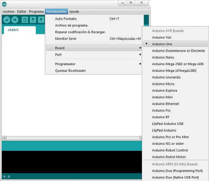
Next, we open the Arduino IDE. We select the board model we are using.
We select the communication port to which it is connected.
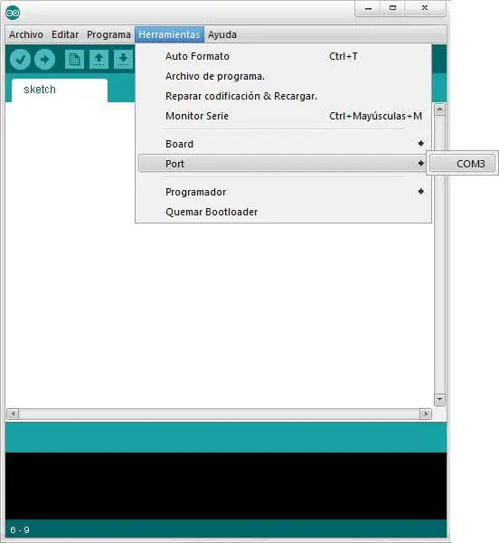
- In Windows it will be something like COM1, COM3…
- In Linux it will be like /dev/ttyACM0
We now have the connection configured and ready to load our first program.
Loading an Example
Finally, we click the highlighted button to compile and send the program to our Arduino board. After a few seconds, the IDE will compile the program and the screen should look similar to the following.
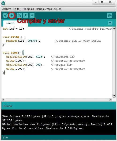
After a few blinks, the board will start executing the program, turning the LED on and off.
Congratulations! If you’ve made it this far it means everything is working and properly configured, and from here you are ready to start playing 🎉.
