
We continue with the posts in the PCB design section by looking at the size of PTH components.
I won’t deny that it’s not exactly the most fun part of PCB design, but it’s necessary to keep in mind the size of the things you are assembling.
Because nothing will be less amusing than finishing a design, buying the PCBs, waiting for them to arrive, and having to throw them away upon discovering that one of the components doesn’t fit because the size is incorrect.
Therefore, it’s convenient to know by heart the sizes of the components we are going to use, and the dimensions that will typically appear when designing a PCB.
So in this post, we are going to look at sizes and dimensions of PTH components.
Make It in Inches, Please
The first thing to know is that PCB design is heavily dominated by the imperial system of units.
I know, we all love the metric system. But, it’s a lost battle. In PCBs, many dimensions are given in inches. Accept it, and don’t try to fight it.
Another measurement you will use frequently is “mil,” which means thousandths of an inch. That is, 0.0254mm. It’s used when talking about track width and hole diameter, for example.
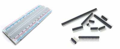
Standard 0.1 Size
Thus, you will frequently find the dimension 0.1 inches. That is, 100mil or 2.54mm. It’s one of the standard pitches for PTH components.
When you see a breadboard or a protoboard, the pitch between holes is precisely 0.1”. It’s also the pitch on Dupont connectors that we are so used to.
Size of PTH Passive Components
Regarding the size of axial resistors, they are usually standardized based on the power rating.
| Power (W) | Length (mm) | Diameter (mm) |
|---|---|---|
| 1/8 | 3.0 | 1.8 |
| 1/4 | 6.5 | 2.5 |
| 1/2 | 8.5 | 3.2 |
| 1 | 11 | 5 |
In the case of coils, some of them have the same axial format as resistors. The size is usually referenced based on the power rating of a resistor of the same size.
Regarding other resistor formats, and capacitors, it’s best to consult the dimensional information from the vendor.
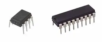
PTH Packages
Regarding integrated circuit formats, logically there is a great variety, so we are only going to look at the most representative ones.
One of the best known is the DIP format, with a different number of pins.
In the DIP format, the distance between pins is (oh yes, you guessed it) 0.1”, that is, 2.54mm.
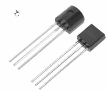
Another common format is the TO92 package, which you will find in transistors, voltage regulators. In this case, the pin pitch is 0.05” (1.27mm), although it’s not too problematic as they are thin enough to bend and adopt a 0.1” spacing.
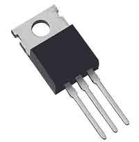
The other common format we are going to look at is TO220, used by a large number of components including transistors, or voltage regulators. In this case, the pin pitch is (here it comes again) 0.1”.
Pad Size
Regarding the size of the pads for inserting PTH components, we must define the inner size (of the hole), and the outer size (of the copper).

Every craftsman has their own methods, but personally, I like 33.46mil (0.85mm) for the inner diameter, and 66mil (1.67mm) for the outer diameter.
With that size, the components fit snugly but not forced, while holding quite well in place, for example when flipping over to solder. And, the copper size is adequate for soldering, without being too big or too small.
On the other hand, it’s worth mentioning that there are different types of pads: circular, rectangular, oblong (or oval) centered or offset.
There is no strict rule about when to use each shape. But, for example, it’s common to use a square for the first pin, to make it easy to identify the component orientation when placing it.
In any case, whatever criterion you adopt, what is important is that you are consistent within the same design.
