In the posts of the series dedicated to the STM32 we have seen that there were three ways to program the STM32 with the Arduino environment. In this post we will see the second one, programming the STM32 with an ST-Link v2.
Just like in the previous post where we saw how to program the STM32 with a USB-TTL converter we will use the BluePill development board, one of the most popular among Makers due to its low cost and “similar” format to an Arduino Nano.
This time we will see how to program the STM32 with an ST-Link v2, which is much more convenient than using a simple USB-TTL converter. The connection is simpler, it avoids having to move the board’s jumpers and, in addition, it allows us to have debug functions (if the IDE we use allows it).
But let’s start by seeing what the ST-Link v2 is and how to use it to program development boards based on the STM32.
What is the ST-Link v2?
The ST-Link v2 is a programmer/debugger built by ST Microelectronics that allows programming and debugging STM8 and STM32 processors. The ST-Link v2 implements SWIM (Single Wire Interface Module) and JTAG/SWD (Serial Wire Debugging) to communicate with the processors on the development board.
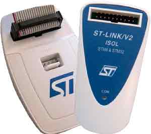
The original ST-Link v2 is a bit expensive, with a cost of 20-25€. An alternative is to use a development board like the ST Discovery or the ST Nucleus, which incorporate an ST-Link v2 on the board itself, at a similar or even lower cost.
Fortunately, there are quite a few ST-Link v2 clones at a much lower price of 1.5-1.6€, which is more or less in the range of a USB-TTL converter.
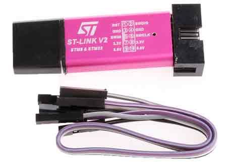
Normally these clone devices have a USB format and, internally, maintain the same electronic schematic as the original (which, by the way, uses an STM8 or 32 inside).
The firmware of these ST-Link v2 clones is extracted from the original (something that may not be entirely legal, but that’s their problem). Therefore, the behavior is also identical to the original.
However, we can also overwrite the firmware of the ST-Link v2 clone, as it has a DFU bootloader. For example, we can convert it into a Black Magic Probe, something we will see in a future post.
For the price it has, an ST-Link v2 clone is a good buy if we are going to frequently use development boards with STM32 or similar.
How to use the ST-Link v2
The process of programming the STM32 with the ST-Link v2 is very simple, even more so than using a USB-TTL.
First, we must install the drivers from the ST website. The drivers are free, but we will have to register to download them. From the folder we download, we run ‘install_drivers.bat’ as administrator.
We connect the device and make sure our system recognizes it correctly.
![]()
Now that we have the ST-Link v2 ready, we connect it to the STM32 according to the following schematic, requiring only 4 cables.
| ST-Link v2 | STM32 |
|---|---|
| SWDIO | DIO |
| SWCLK | CLK |
| 3.3V | 3.3V |
| GND | GND |
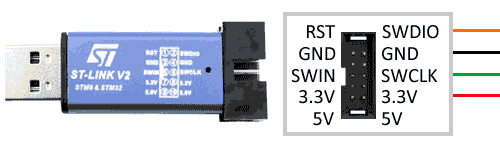
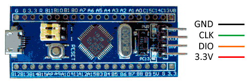
Check the pin assignment on your development board and your ST-Link v2 programmer, because manufacturers tend to change them around.
Do not power the device simultaneously via the ST-Link v2 while it is also connected via the BluePill’s micro-USB, or we could damage the device.
Programming STM32 with ST-Link v2
Let’s check that everything works correctly, and upload a sketch to the STM32 Blue Pill. We assume you have the Arduino IDE correctly configured (right?) as we saw in the previous post.
We will upload the same blink file, which, as we know, we use as a “hello world” for processors, and which we saw adapted for the STM32 in the previous post. For your convenience, here is the code again.
//const int ledPIN = PB1;  //this is what comes in the example but doesn't work
const int ledPIN = PC13;  // depends on each board

void setup()
{
  pinMode(ledPIN, OUTPUT);
}

void loop()
{
  digitalWrite(ledPIN, HIGH);
  delay(1000);
  digitalWrite(ledPIN, LOW);
  delay(1000);
}
Now, in the Arduino IDE configuration, we choose the ‘ST-Link’ uploader.
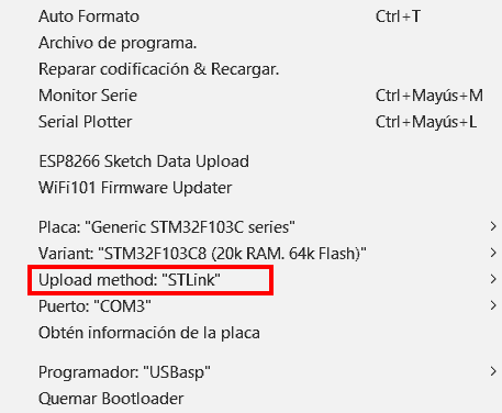
And that’s it, we click upload. Unlike with the USB-TTL converter, we don’t have to change any jumpers, or touch anything on the board. The board’s integrated LED will start blinking slowly, which means everything went well.
That easy! In the third and final post about ways to program the STM32 we will learn to program it directly with the Arduino environment via the board’s micro USB, the “most difficult” but also the most useful of the three ways we are going to see. See you next time!