In this post, we are going to see how to program the STM32 with the Arduino environment, or any other Arduino-based IDE. In particular, we are going to use the BluePill development board we saw in the previous entry.
Using the Arduino IDE (or others based on it) to program the STM32 is a great advantage from the point of view of convenience and utility, allowing us to use a simple and well-known environment.
Furthermore, it will allow us to take advantage of many tools created by the Arduino community. Although it should be noted that many libraries will need modifications to make them work on an STM32.
We have, at least, three ways to program the STM32 with Arduino-based environments.
- With a USB-TTL converter
- With an ST-Link programmer
- Directly through the micro-USB port
In this post we will focus on the first method, programming the STM32 using a USB-TTL converter. Although it is not the most useful of the three, it will serve to introduce the installation of the necessary files to work with the Arduino IDE.
Configure the Arduino Environment
For the Arduino IDE (or other Arduino-based IDEs) to work with STM32 boards, it is necessary to add them to the board manager.
Arduino does not officially support development boards based on the STM32. But, fortunately, thanks to the work of Roger Clark and the community his work has generated, we have the STM32 available as an unofficial extension.
The STM32 compatibility code repository for Arduino is Open Source and is available at this link. This, in turn, is based on the work developed by Leaflabs for the Maple board, very similar to the BluePill.
To add the board definitions we are going to use the configuration file provided by www.stmduino.com, a website that encompasses a large part of the STM32 community around Arduino.
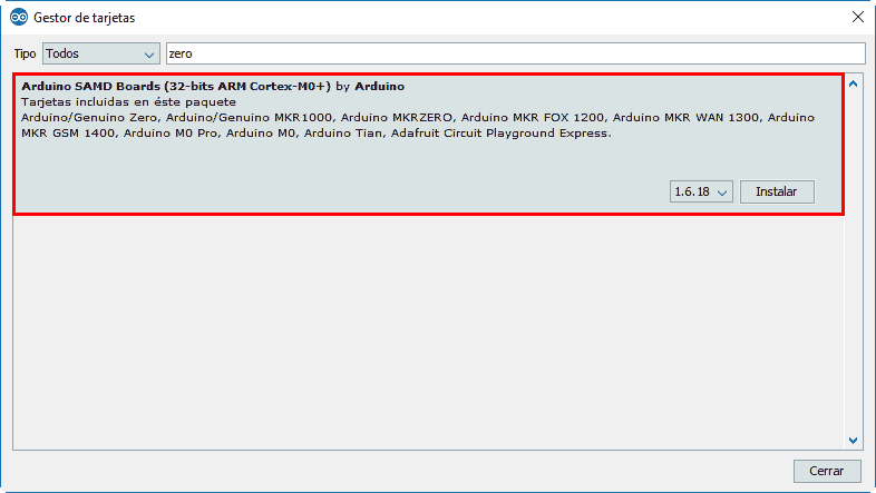
First, we open the Arduino IDE and go to the board manager (Tools/Board/Board Manager…). Here we add support for SAND boards (Zero or similar). The STM32 toolchain needs files from these ARM boards for compilation (specifically “arm-none-eabi-g++”).
Next, we go to preferences and, in “Additional Boards Manager URLs”, click the button on the right and paste the following address into the window that appears.
dan.drown.org/stm32duino/package_STM32duino_index.json
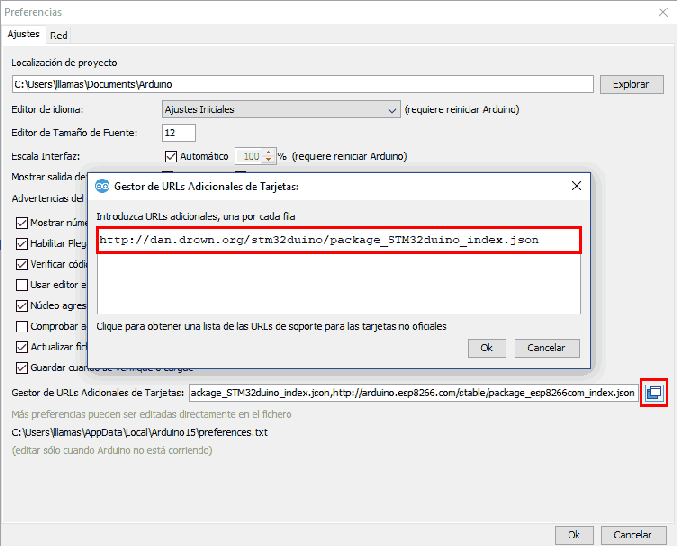
If we already had some definition (ESP8266, Digispark) we will put one line per board.
We return to the board manager, and we will have the STM32 boards available. We install the ones we need. In particular, for the BluePill (STM32F103C8T6) we are going to need the STM32F1X.
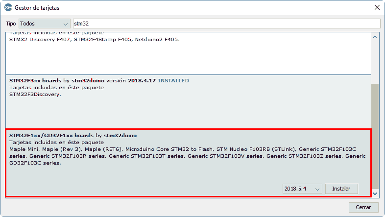
And now we can program our BluePill with Arduino!
Connect the STM32 USB-TTL Converter
In this first post we are going to program the STM32 via UART, so we are going to need a USB-TTL converter. These USB to TTL converters are cheap, very useful devices that can be found on AliExpress or eBay for between €0.70 to €2.
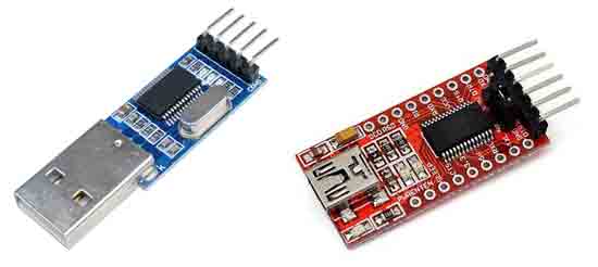
The STM32 supply voltage is 3.3V, so we have to ensure that our TTL converter works at 3.3V. They usually work at both 5V and 3.3V, and the output voltage can be selected with a configuration jumper, either on the board or on the output pins.
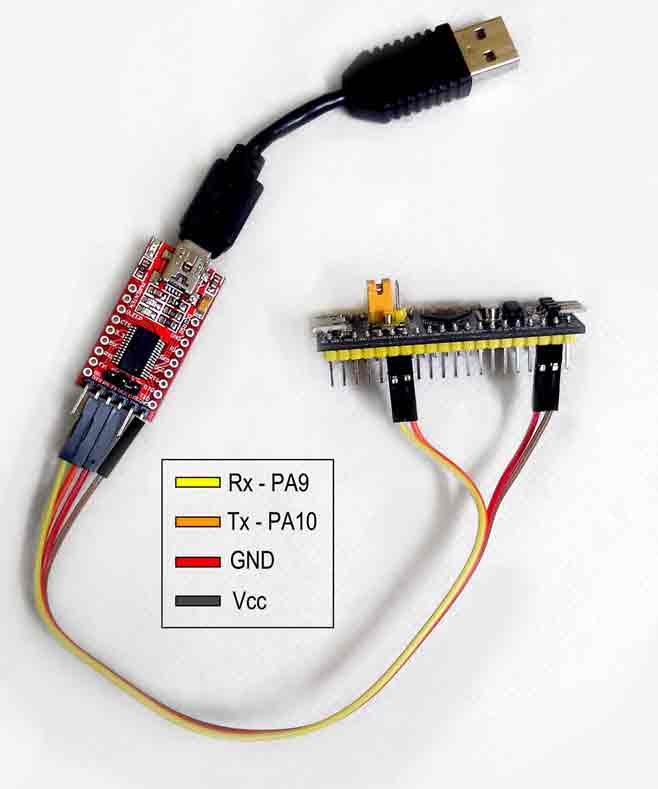
To program the STM32 we must connect the communication pins of the USB-TTL converter (TX and RX) to the UART1 pins of the STM32, which are A10 and A9. Therefore, the connection is as follows,
| USB-TTL | STM32 |
|---|---|
| TX | A10(PA10) |
| RX | A9 (PA9) |
| 3.3V | Vcc |
| Gnd | Gnd |
So the setup looks like the following image,
Program STM32 with Arduino
With the default bootloader, the STM32 has two boot modes that depend on the state of the BOOT0 pin.
| BOOT0 | MODE |
|---|---|
| LOW | Normal: Boot the last program in flash |
| HIGH | Programming: Waits for a program via UART. When it receives it, it writes it to flash and then starts it |
Therefore, to program the STM32 it is necessary to set the BOOT0 pin to HIGH and to return to normal operation it is necessary to set it to LOW.
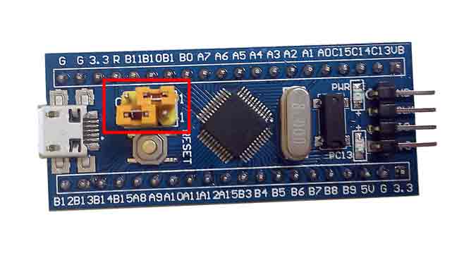
To make it simple (though not as simple as on Arduino boards) the BluePill boards have configuration jumpers. To be able to program the BluePill via UART we have to move the BOOT0 jumper to position 1.
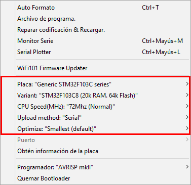
Now, we connect the USB-TTL converter to the computer and select the generic STM32F103C board,
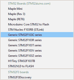
And the following configuration parameters,
To test that everything works correctly we are going to try with the well-known Blink, the equivalent of “Hello world” on development boards, which simply blinks the LED integrated on the board.
Therefore, we paste the following text into the Arduino IDE.
//const int ledPIN = PB1;  //this is what comes in the example but doesn't work
const int ledPIN = PC13;  // depends on each board

void setup()
{
  pinMode(ledPIN, OUTPUT);
}

void loop()
{
  digitalWrite(ledPIN, HIGH);
  delay(1000);
  digitalWrite(ledPIN, LOW);
  delay(1000);
}
We load it onto the board and the LED should start blinking. This is because the bootloader is configured to execute the program immediately after loading.
However, if we disconnect and reconnect the SMT32F we will see that the LED does not blink, because it is still in upload mode. We have to put the BOOT0 jumper back to position 0 for the STM32 to execute the loaded program on startup.
The STM32 library has quite a few examples that we can investigate to delve deeper into this interesting board. We’ll get to that little by little! In the upcoming posts of the STM32 series we will see how to program it with an ST-Link and directly through the micro-usb.