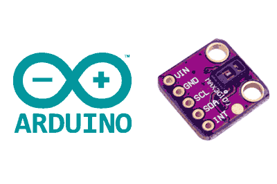
What is a MAX30102?
The MAX30102 is a sensor from manufacturer Maxim Integrated that incorporates the functions of a pulse oximeter and an oximeter into a single integrated circuit that we can use with a processor like Arduino.
The MAX3010x series is an optical sensor, which operates based on the different behavior that blood has in response to light, depending on its oxygen saturation level.
To do this, the MAX30102 incorporates two LEDs, one of red spectrum and the other of infrared. The MAX30102 is placed on the skin, for example, on the finger or wrist. The sensor detects the reflected light and determines the degree of saturation.
Communication with the MAX30102 is done through the I2C bus, making it very easy to connect it to a processor like Arduino.
The MAX30102 requires dual power supplies of 1.8V for logic and 3V3 for the LEDs. Normally, it is found in 5V modules that incorporate the necessary level adaptation.
The MAX30102 is a widely used sensor in DIY projects. A common and striking example is to use it with an OLED screen to display the pulse.
The MAX30102 is a low-cost sensor designed for wearables and is not suitable for medical applications. Do not use it in applications that depend on people’s health.
Price
The MAX30102 sensors are quite cheap. We can find modules for about €1.65 from international sellers on Ebay and Aliexpress.
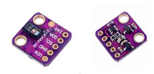
There are different types of modules. Avoid buying the green ones, as they have a design defect that causes them to not work properly.
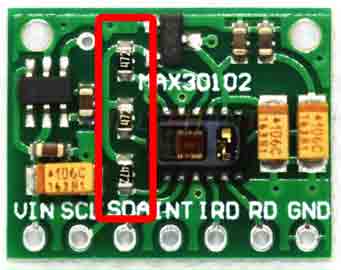
If you have one of these green modules, you may be able to get it to work by removing the resistors in the following image.
How does a MAX30102 work?
Optical pulse oximetry is a non-invasive method to determine the percentage of blood oxygen saturation. Its operation is based on the fact that hemoglobin (Hb) and oxygenated hemoglobin (HbO2) have different light absorption coefficients for different wavelengths.
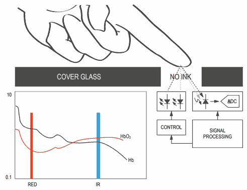
Oxygenated blood absorbs more infrared light, while poorly oxygenated blood absorbs more red light. In parts of the body where the skin is thin enough to allow blood vessels to pass through, this difference can be used to determine the degree of saturation.
The MAX30102 incorporates two LEDs, one of red spectrum (660nm) and the other of infrared (880nm), as well as photodiodes to measure the reflected light and an 18-bit ADC with a sampling frequency of 50sps (samples per second) at 3200sps.
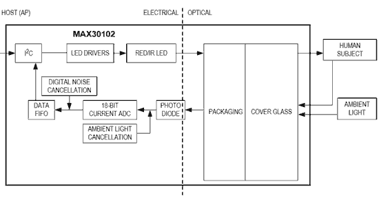
It also has the necessary electronics for amplification and signal filtering, cancellation of ambient light, rejection of 50-60Hz frequencies (artificial light), and temperature compensation.
The module’s consumption is up to 50mA during measurement, although the intensity can be adjusted by programming, with a low power mode of 0.7µA during measurements.
Assembly diagram
The connection is simple, we simply power the module from Arduino using GND and 5V and connect the SDA and SCL pins of Arduino to the corresponding pins of the MAX30102.
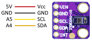
While the connection from the Arduino side would look like this.
In Arduino Uno, Nano, and Mini Pro, SDA is pin A4 and SCK is pin A5. For other Arduino models, consult the corresponding pinout diagram.
Verify that your board is compatible with 5V before connecting it to Arduino. If not, you will need to use a logic level adapter.
Code examples
Reading the MAX30102 can be somewhat complex as it involves a lot of signal processing to obtain meaningful values.
There are several libraries to facilitate its use. One of them is the library developed by SparkFun, available at https://github.com/sparkfun/SparkFun_MAX3010x_Sensor_Library.
The library is compatible with the MAX30100, MAX30102, and MAX30105 sensors, although the latter has an additional green sensor that the others do not have. It provides code examples, which it is advisable to review. The following examples, for instance, are modifications based on those available in the library.
Pulse Oximeter and Oximeter
The following example shows the code necessary to obtain the values of saturation and heart rate with the MAX30102.
```cpp
#include <Wire.h>
#include "MAX30105.h"
#include "spo2_algorithm.h"

MAX30105 particleSensor;


#define MAX_BRIGHTNESS 255


#if defined(__AVR_ATmega328P__) || defined(__AVR_ATmega168__)
//Arduino Uno doesn't have enough SRAM to store 100 samples of IR led data and red led data in 32-bit format
//To solve this problem, 16-bit MSB of the sampled data will be truncated. Samples become 16-bit data.
uint16_t irBuffer[100]; //infrared LED sensor data
uint16_t redBuffer[100];  //red LED sensor data

#else
uint32_t irBuffer[100]; //infrared LED sensor data
uint32_t redBuffer[100];  //red LED sensor data

#endif

int32_t bufferLength; //data length
int32_t spo2; //SPO2 value
int8_t validSPO2; //indicator to show if the SPO2 calculation is valid
int32_t heartRate; //heart rate value
int8_t validHeartRate; //indicator to show if the heart rate calculation is valid

byte pulseLED = 11; //Must be on PWM pin
byte readLED = 13; //Blinks with each data read

void setup()
{
  Serial.begin(115200); // initialize serial communication at 115200 bits per second:

  pinMode(pulseLED, OUTPUT);
  pinMode(readLED, OUTPUT);

  // Initialize sensor
  if (!particleSensor.begin(Wire, I2C_SPEED_FAST)) //Use default I2C port, 400kHz speed
  {
    Serial.println(F("MAX30105 was not found. Please check wiring/power."));
    while (1);
  }

  Serial.println(F("Attach sensor to finger with rubber band. Press any key to start conversion"));
  while (Serial.available() == 0) ; //wait until user presses a key
  Serial.read();

  byte ledBrightness = 60; //Options: 0=Off to 255=50mA
  byte sampleAverage = 4; //Options: 1, 2, 4, 8, 16, 32
  byte ledMode = 2; //Options: 1 = Red only, 2 = Red + IR, 3 = Red + IR + Green
  byte sampleRate = 100; //Options: 50, 100, 200, 400, 800, 1000, 1600, 3200
  int pulseWidth = 411; //Options: 69, 118, 215, 411
  int adcRange = 4096; //Options: 2048, 4096, 8192, 16384

  particleSensor.setup(ledBrightness, sampleAverage, ledMode, sampleRate, pulseWidth, adcRange); //Configure sensor with these settings
}

void loop()
{
  bufferLength = 100; //buffer length of 100 stores 4 seconds of samples running at 25sps

  //read the first 100 samples, and determine the signal range
  for (byte i = 0 ; i < bufferLength ; i++)
  {
    while (particleSensor.available() == false) //do we have new data?
      particleSensor.check(); //Check the sensor for new data

    redBuffer[i] = particleSensor.getRed();
    irBuffer[i] = particleSensor.getIR();
    particleSensor.nextSample(); //We're finished with this sample so move to next sample

    Serial.print(F("red="));
    Serial.print(redBuffer[i], DEC);
    Serial.print(F(", ir="));
    Serial.println(irBuffer[i], DEC);
  }

  //calculate heart rate and SpO2 after first 100 samples (first 4 seconds of samples)
  maxim_heart_rate_and_oxygen_saturation(irBuffer, bufferLength, redBuffer, &spo2, &validSPO2, &heartRate, &validHeartRate);

  //Continuously taking samples from MAX30102.  Heart rate and SpO2 are calculated every 1 second
  while (1)
  {
    //dumping the first 25 sets of samples in the memory and shift the last 75 sets of samples to the top
    for (byte i = 25; i < 100; i++)
    {
      redBuffer[i - 25] = redBuffer[i];
      irBuffer[i - 25] = irBuffer[i];
    }

    //take 25 sets of samples before calculating the heart rate.
    for (byte i = 75; i < 100; i++)
    {
      while (particleSensor.available() == false) //do we have new data?
        particleSensor.check(); //Check the sensor for new data

      digitalWrite(readLED, !digitalRead(readLED)); //Blink onboard LED with every data read

      redBuffer[i] = particleSensor.getRed();
      irBuffer[i] = particleSensor.getIR();
      particleSensor.nextSample(); //We're finished with this sample so move to next sample

      //send samples and calculation result to terminal program through UART
      Serial.print(F("red="));
      Serial.print(redBuffer[i], DEC);
      Serial.print(F(", ir="));
      Serial.print(irBuffer[i], DEC);

      Serial.print(F(", HR="));
      Serial.print(heartRate, DEC);

      Serial.print(F(", HRvalid="));
      Serial.print(validHeartRate, DEC);

      Serial.print(F(", SPO2="));
      Serial.print(spo2, DEC);

      Serial.print(F(", SPO2Valid="));
      Serial.println(validSPO2, DEC);
    }

    //After gathering 25 new samples recalculate HR and SP02
    maxim_heart_rate_and_oxygen_saturation(irBuffer, bufferLength, redBuffer, &spo2, &validSPO2, &heartRate, &validHeartRate);
  }
}
