In this post, we are going to learn how to read the position value of a potentiometer. Potentiometers are devices that we will frequently use to introduce analog values into our Arduino (for example, to regulate the light intensity of an LED, the speed of a DC motor, or the position of a servo).
Measuring the value of a potentiometer is similar (though not identical) to measuring an unknown resistance, something we saw in this post.
The concepts we saw are necessary to understand the content of this post, so if you haven’t done so yet, I recommend reading it.
What is a potentiometer?
A potentiometer is a device that allows its resistance to be varied manually, between a minimum value Rmin (usually 0 ohms) and a maximum value Rmax. Common values for Rmax are 5k, 10k, or 20k ohms.
Internally, a potentiometer consists of a moving contact that slides along a resistive track. In this way, when we move the potentiometer, we move the contact along the track, varying the length of the track segment we are in contact with, and thus varying its resistance.
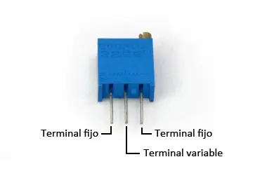
Normally, a potentiometer has three terminals.
- The two ends are connected to both sides of the track, so they will always register the maximum resistance Rmax.
- The remaining terminal corresponds to the moving contact, and it is where the resistance varies.
This terminal varies its resistance relative to the other two terminals as we operate the potentiometer, with the sum of the resistance to the other terminals being equal to Rmax.
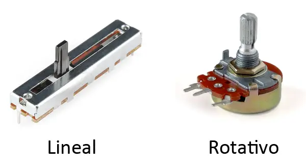
Regarding geometry, we can find linear or rotary type potentiometers.
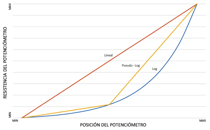
Finally, regarding the relationship between position and resistance, we find potentiometers of linear, parabolic, or exponential type.
- Linear ones have a proportionality between resistance and displacement, which means more intuitive behavior.
- Exponential ones allow for greater precision at low resistance values, making them suitable when fine adjustment over a wide range is needed.
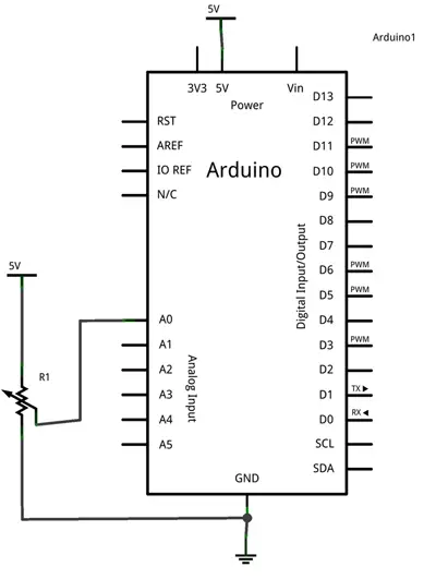
Electrical Schematic
The schematic is similar to the one used to measure a variable resistance, with one important exception. We do not need a calibration resistor because the potentiometer itself acts as a voltage divider.
On the other hand, the resistance between the terminals is always the Rmax of the potentiometer, whereas in the case of a calibration resistor it would be Rs+Rc, so the equations vary slightly.
The final schematic is as follows.
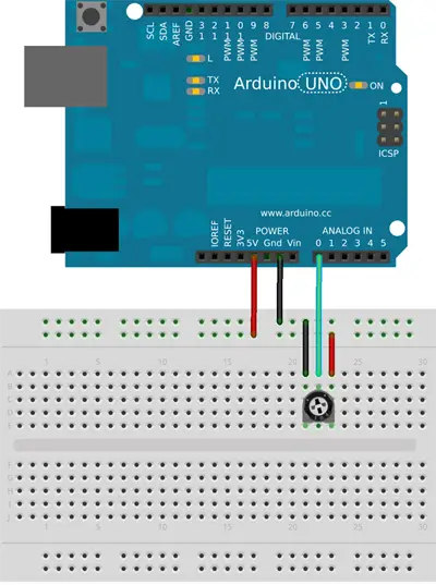
Assembly
The necessary assembly is shown in the following image.
Code
The code to read the potentiometer’s position is really simple. We simply use an analog input to read the voltage value and convert it to position by interpolating with the “map” function.
const int analogPin = A0;
int value;      // variable to store the raw analog reading
int position;   // position of the potentiometer as a percentage

void setup() {
}

void loop() {
  value = analogRead(analogPin);       // perform the raw analog reading
  position = map(value, 0, 1023, 0, 100);  // convert to percentage

  //... do whatever you want with the measured position value

  delay(1000);
}
Download the Code
All the code from this post is available for download on GitHub. 
