In the tutorial Digital Inputs in Arduino we saw how to read a sensor that provides a digital signal with two voltage levels, LOW and HIGH. We left pending how to use digital inputs to read the state of a switch or push button with Arduino.
To do this, we will need to correctly perform a specific setup and the help of two new friends: Pull Down and Pull Up resistors. Although both cases are very similar, the setup and the type of resistor to use will depend on whether we want to read a LOW or HIGH value when the button or switch is pressed.
To understand how both setups work, we will present the logical reasoning that leads to them. For this, we will use two incorrect setups that will help us understand the role of each element in the final, correct setup.
So, let’s start with the first attempt to read the button state.
A more advanced way to read a button is to use interrupts and apply debounce to filter the input, as we see in this post
First Attempt, Direct Connection
Our first idea to read a button could be to directly connect a digital PIN of Arduino to a reference voltage, be it 0V or 5V.
When the button is closed, the voltage at the PIN would be the reference value (0V or 5V depending on the setup) and we could perform the reading as with any digital input.
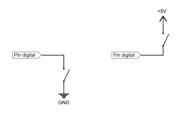
What’s the problem? Well, this will work when the switch is closed. But, what happens when the switch is open? In this case, we are leaving the PIN completely disconnected from any voltage (something we will call a high impedance state).
What value does an input register if we take a measurement in a high impedance state? It depends on several factors, such as the internal construction of the input or the last state it was connected to.
In summary, the input is in an indeterminate state (meaning it can assume any value). Therefore, it is necessary to avoid this situation in our designs.
How can we resolve this indeterminate state? Well, this leads us directly to our second attempt. 👇
Improving Our Solution, Double Connection
The next thing we might think is to connect the PIN to two voltage references, alternated based on the switch state:
To measure a LOW value when the switch is pressed
- We can connect the PIN fixed to 5V, and to 0V through the switch.
- With the switch open we would read
HIGH. - When the switch is closed, 0V would be forced on the PIN, so we would read
LOW.
To measure a HIGH value when the switch is pressed
- We can connect the PIN fixed to 0V, and to 5V through the switch.
- With the switch open we would read
LOW. - When the switch is closed, 5V would be forced on the PIN, so we would read
HIGH.
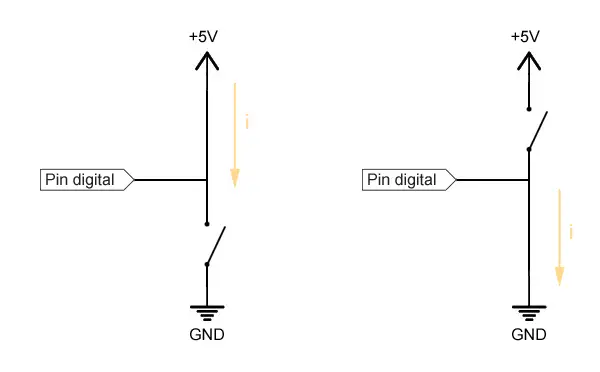
What’s the problem with this setup? Well, when pressing the switch we are directly connecting the 0V and 5V values, which means we are causing a short circuit.
This would cause a high current flow and rapid heating of components and conductors (death, destruction, getting fired…).
How to avoid this short circuit? Well, we are close. We’ll see this next in the definitive setup.
Short circuits are dangerous faults. Besides damaging a component, you could even cause a fire. Be careful.
The setup wouldn’t work either because we would be connecting the PIN simultaneously to 0V and 5V, so we would again have an indeterminacy, and the actual measurement would depend on the resistance of the conductors to both voltage levels.
Correct Setup, Pull-Down or Pull-Up Resistors
As we had anticipated, to correctly solve the setup we will need the presence of two new friends, Pull Down and Pull Up resistors. These two resistors are a basic mechanism, very common in the world of electronics and automation.
Pull-Down and Pull-Up resistors are connected between the digital PIN and one of the reference voltages (0V or 5V) and “force” or “pull” (hence their name) the voltage value to LOW or HIGH, respectively.
The Pull-Up resistor:
- Forces
HIGHwhen the button is open. - When closed, the PIN is set to
LOW, the current that flows is limited by this resistor.
The Pull-Down resistor:
- Forces
LOWwhen the button is open. - When closed, the PIN is set to
HIGH, and the current that flows is limited by this resistor.
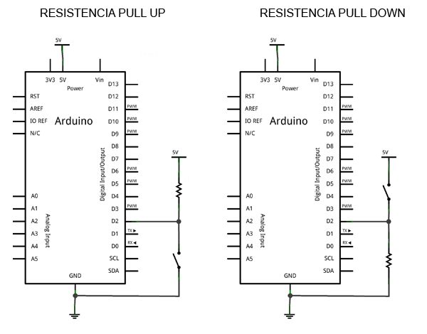
This is how the final setup would look in a schematic view (the connection can be made using any of the digital PINs).
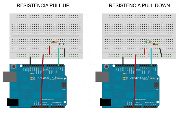
And this is the wiring on a breadboard.
Finally, reading the state of the PIN is done normally, just as we saw in the tutorial Digital Inputs in Arduino.
const int inputPin = 2;

int value = 0;

void setup() {
  Serial.begin(9600);
  pinMode(inputPin, INPUT);
}

void loop(){
  value = digitalRead(inputPin);  //digital reading of pin

  //send message to serial port based on the value read
  if (value == `HIGH`) {
      Serial.println("On");
  }
  else {
      Serial.println("Off");
  }
  delay(1000);
}
Arduino has internal 30k Pull Up resistors but they are not usually used for two reasons.
- They have low authority (resistance value too high).
- If we configure them incorrectly from the program, we can generate a short circuit, so it is preferable to connect them physically to verify we haven’t forgotten them.
What resistor value to choose?
The resistor value is conditioned by the current that flows when the switch is actuated, and by a concept called the “authority of the Pull Down/Up” which is related to noise in the measurement.
A very small resistor
- 👍 Will have high authority.
- 👎 But will allow a higher current flow, which means higher consumption and more heating.
A very large resistor
- 👍 Will allow little current to pass.
- 👎 But will have low authority, making it more susceptible to incorrect measurements due to noise.
Download the Code
All the code from this post is available for download on Github. 
