In this post, we are going to use Arduino to measure the electrical resistance of a device. Why is this interesting? Why not just use a multimeter and be done with it?
Well, the reason we want to measure resistances is that many sensors provide their measurement through a variation in their resistance. To use these sensors (light, temperature) we need to be able to measure their resistance from Arduino.
Unfortunately, in Arduino (and in general, practically in no PLC) we do not have an input to directly measure resistances. The only thing we can measure are digital or analog voltage signals.
But we can use these, and a small setup we are going to make, to easily measure the value of an unknown resistance by comparison with a known one.
In this post we are going to intensively use the analog inputs, so it is assumed that you are familiar with their use. If not, it is advisable to visit this post “Analog Inputs in Arduino”, where we saw how to use Arduino’s analog inputs.
Electrical Schematic and Setup
As we said, our processor cannot measure resistances, nor electrical currents. The only thing we can measure are voltages digitized through its inputs.
However, we can take advantage of the analog inputs to easily measure the value of an unknown resistance, by comparison with another. We will call the known resistance the calibration.
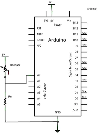
The setup we need is a simple voltage divider between the unknown value resistor and our calibration resistor. The electrical schematic we need is the following.
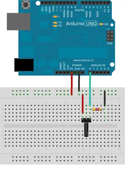
While the setup on a breadboard would be the following.
Sometimes you will hear this resistor incorrectly called a Pull-Down resistor because they occupy similar places in the electrical setup, as we saw in the post Reading a Button with Arduino).
However, the functionality of these resistors is different (so make me happy and call it the calibration resistor 😙)
Example Code
The code needed to perform the reading is simple. We simply read the voltage value through the analog input, and use the voltage divider equations to obtain the value of the measured resistance.
const int sensorPin = A0;
const int Rc = 1500;  // value of the calibration resistance

int V;          // stores the measured value
long Rsensor;      // stores the calculated resistance

void setup() {
}

void loop() {
  V = analogRead(sensorPin);    // perform the reading
  Rsensor = 1024L * Rc / V - Rc;   // calculate the value of the resistance

  //... we would do whatever we wanted with Rsensor

  delay(1000);
}
You will notice that we have performed all calculations using integer arithmetic, intentionally avoiding using float type variables. The reason is that floating-point operations occupy a large amount of memory and are significantly slower.
Whenever possible, avoid using floating-point operations. There are multiple techniques to perform similar operations with integer arithmetic, without losing much precision.
The Value of the Calibration Resistor
The only thing left is to choose the value of the calibration resistor. The answer is not unique, and its value will depend entirely on the range of resistances the sensor can adopt during its operation.
In general, the value to choose will depend on:
Large enough to limit the current flowing through the sensor when it reaches its minimum value. (For example, if the sensor can reach 0 Ohms, the only resistor limiting the current will be the calibration resistor).
Small enough compared to the sensor’s to limit the loss of measurement precision. (For example, if the sensor’s resistance reaches the same value as the calibration resistor, we will be losing half of the available precision).
As a guide, common values for this resistor are usually 1k to 4.7k, although as we said it depends on the sensor’s resistance range.
You can use our voltage divider calculator to determine the value of the calibration resistor, the current it will withstand, and the loss of precision.
Download the Code
All the code from this post is available for download on Github. 
