What is a CC1101?
The CC1101 is an RF transceiver for frequencies below 1Ghz, which we can use with a processor like Arduino to send or receive data by radio frequency.
The CC1101 can work at any frequency within the bands 300 to 348Mhz, 387 to 464Mhz, and 779 to 928Mhz. This includes the ISM band, for use without the need for a license.
In some countries, it is illegal to use some of these bands. Check the current legislation in your country before applying the content of this post.
It supports different modulation formats (2-FSK, 4-FSK, GFSK, and MSK), and the transmission speed is up to 0.6 Kbps to 600 Kbps.
The programmable output power, for all supported frequencies, is up to +10 dBm. The range is up to 100-150 meters, depending on the frequency.
The operating voltage is 1.8 to 3.6V. Communication is done through SPI, so it is easy to use it with a processor.
The CC1101 is one of the best and most robust options to provide our project with RF transmission, especially in those that incorporate 3V3 processors like the ESP8266/ESP32.
Price
CC1101 devices are inexpensive. We can find them with a “spring-type” antenna for about €1.30 from international sellers on Ebay and Aliexpress.
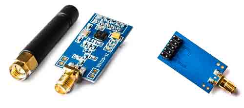
However, I recommend that you buy the models with a standard connector antenna, which are a bit more expensive at €2.30 but have better performance.
Assembly diagram
The CC1101 operates at 3.3V and is not tolerant to 5V. Most modules do not incorporate any type of adaptation, so connecting them to 5V will damage the CC1101.
If your processor is 3.3V, such as the ESP8266 or ESP32, you will not have any problems. But, if your processor is 5V, you will need to use a level shifter as we saw here.
Apart from this, the connection scheme is simple, since the CC1101 uses the SPI bus for communication. Therefore, the connection seen from the processor is as follows.
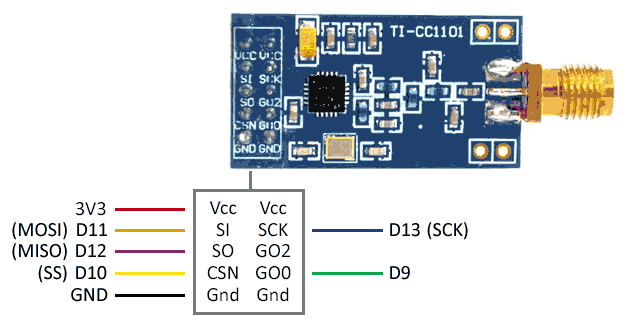
The connection, seen from Arduino, will be as follows.
CC1101 modules are not normally compatible with 5V. If not, and your processor is not 3.3V, you will have to use a level shifter.
Code examples
Basic example
To use the CC1101, we will use the SmartRC-CC1101 library available at this link.
The library includes several usage examples that are worth reviewing. The code below is a simplified code based on the library’s examples.
Transmitter
//New transmission method.
//In addition, the gdo0 and gdo2 pin are not required.
//https://github.com/LSatan/SmartRC-CC1101-Driver-Lib
//by Little_S@tan

#include <ELECHOUSE_CC1101_SRC_DRV.h>

const int n = 61;
byte buffer[n] = "";

void setup() {

    Serial.begin(9600);

    if (ELECHOUSE_cc1101.getCC1101()){         // Check the CC1101 Spi connection.
    Serial.println("Connection OK");
    }else{
    Serial.println("Connection Error");
    }

    ELECHOUSE_cc1101.Init();              // must be set to initialize the cc1101!
    ELECHOUSE_cc1101.setCCMode(1);       // set config for internal transmission mode.
    ELECHOUSE_cc1101.setModulation(0);  // set modulation mode. 0 = 2-FSK, 1 = GFSK, 2 = ASK/OOK, 3 = 4-FSK, 4 = MSK.
    ELECHOUSE_cc1101.setMHZ(433.92);   // Here you can set your basic frequency. The lib calculates the frequency automatically (default = 433.92).The cc1101 can: 300-348 MHZ, 387-464MHZ and 779-928MHZ. Read More info from datasheet.
    ELECHOUSE_cc1101.setSyncMode(2);  // Combined sync-word qualifier mode. 0 = No preamble/sync. 1 = 16 sync word bits detected. 2 = 16/16 sync word bits detected. 3 = 30/32 sync word bits detected. 4 = No preamble/sync, carrier-sense above threshold. 5 = 15/16 + carrier-sense above threshold. 6 = 16/16 + carrier-sense above threshold. 7 = 30/32 + carrier-sense above threshold.
 // ELECHOUSE_cc1101.setPA(10);      // set TxPower. The following settings are possible depending on the frequency band.  (-30  -20  -15  -10  -6    0    5    7    10   11   12) Default is max!
    ELECHOUSE_cc1101.setCrc(1);     // 1 = CRC calculation in TX and CRC check in RX enabled. 0 = CRC disabled for TX and RX.

    Serial.println("Tx Mode");
}

void loop() {

//When sending, we give a little time to completely transmit the message (time in millis).
//You can shorten the time. It depends on the data rate and the packet length. Just try it out for fine tuning.

    if (Serial.available()) {
    int len = Serial.readBytesUntil('\n', buffer, n);
    buffer[len] = '\0';
    Serial.println((char *)buffer);
    ELECHOUSE_cc1101.SendData(buffer, len, 100);
    Serial.print("Buffer: ");
    for (int i = 0; i<len; i++){
    Serial.println(buffer[i]);
    }
    Serial.print("len: ");
    Serial.println(len);
  }
}
Receiver
#include <ELECHOUSE_CC1101_SRC_DRV.h>

void setup(){

    Serial.begin(9600);

    if (ELECHOUSE_cc1101.getCC1101()){         // Check the CC1101 Spi connection.
    Serial.println("Connection OK");
    }else{
    Serial.println("Connection Error");
    }

    ELECHOUSE_cc1101.Init();              // must be set to initialize the cc1101!
    ELECHOUSE_cc1101.setCCMode(1);       // set config for internal transmission mode.
    ELECHOUSE_cc1101.setModulation(0);  // set modulation mode. 0 = 2-FSK, 1 = GFSK, 2 = ASK/OOK, 3 = 4-FSK, 4 = MSK.
    ELECHOUSE_cc1101.setMHZ(433.92);   // Here you can set your basic frequency. The lib calculates the frequency automatically (default = 433.92).The cc1101 can: 300-348 MHZ, 387-464MHZ and 779-928MHZ. Read More info from datasheet.
    ELECHOUSE_cc1101.setSyncMode(2);  // Combined sync-word qualifier mode. 0 = No preamble/sync. 1 = 16 sync word bits detected. 2 = 16/16 sync word bits detected. 3 = 30/32 sync word bits detected. 4 = No preamble/sync, carrier-sense above threshold. 5 = 15/16 + carrier-sense above threshold. 6 = 16/16 + carrier-sense above threshold. 7 = 30/32 + carrier-sense above threshold.
    ELECHOUSE_cc1101.setCrc(1);      // 1 = CRC calculation in TX and CRC check in RX enabled. 0 = CRC disabled for TX and RX.

    Serial.println("Rx Mode");
}
byte buffer[61] = {0};

void loop(){

    //Checks whether something has been received.
    //When something is received we give some time to receive the message in full.(time in millis)
    if (ELECHOUSE_cc1101.CheckRxFifo(100)){

    if (ELECHOUSE_cc1101.CheckCRC()){    //CRC Check. If "setCrc(false)" crc returns always OK!
    Serial.print("Rssi: ");
    Serial.println(ELECHOUSE_cc1101.getRssi());
    Serial.print("LQI: ");
    Serial.println(ELECHOUSE_cc1101.getLqi());

    int len = ELECHOUSE_cc1101.ReceiveData(buffer);
    buffer[len] = '\0';
    Serial.println((char *) buffer);
    for (int i = 0; i < len; i++){
    Serial.print(buffer[i]);
    Serial.print(",");
    }
    Serial.println();
    }
    }
}
Clone device
One of the most common examples when dealing with 315/433Mhz devices is to copy existing signals, as we saw in the entry Copy a 315/433Mhz wireless remote control with Arduino.
We can perform this same function with the CC1101, with some of the following libraries
RC-Switch
It is possible to use the RC-Switch library along with the CC1101. Here is an example
#include <ELECHOUSE_CC1101_SRC_DRV.h>
#include <RCSwitch.h>

int pin; // int for Receive pin.

RCSwitch mySwitch = RCSwitch();

void setup() {
  Serial.begin(9600);


#ifdef ESP32
pin = 4;  // for esp32! Receiver on GPIO pin 4.

#elif ESP8266
pin = 4;  // for esp8266! Receiver on pin 4 = D2.

#else
pin = 0;  // for Arduino! Receiver on interrupt 0 => that is pin #2

#endif

  ELECHOUSE_cc1101.Init();
  //ELECHOUSE_cc1101.setRxBW(812.50);  // Set the Receive Bandwidth in kHz. Value from 58.03 to 812.50. Default is 812.50 kHz.
  //ELECHOUSE_cc1101.setPA(10);
  ELECHOUSE_cc1101.setMHZ(433.92);

  mySwitch.enableReceive(pin);  // Receiver on interrupt 0 => that is pin #2
  ELECHOUSE_cc1101.SetRx();  // set Receive on
}

void loop() {
  if (mySwitch.available())
  {
    output(mySwitch.getReceivedValue(),
    mySwitch.getReceivedBitlength(),
    mySwitch.getReceivedDelay(),
    mySwitch.getReceivedRawdata(),
    mySwitch.getReceivedProtocol());
    mySwitch.resetAvailable();
  }
}
NewRemoteReceiver
It is also possible to use the NewRemoteReceiver library with the CC1101. Here is an example
#include <ELECHOUSE_CC1101_SRC_DRV.h>
#include <NewRemoteReceiver.h>

int pin;

void setup() {
  Serial.begin(115200);


#ifdef ESP32
pin = 4;  // for esp32! Receiver on GPIO pin 4.

#elif ESP8266
pin = 4;  // for esp8266! Receiver on pin 4 = D2.

#else
pin = 0;  // for Arduino! Receiver on interrupt 0 => that is pin #2

#endif

  ELECHOUSE_cc1101.Init();            // must be set to initialize the cc1101!
  //ELECHOUSE_cc1101.setRxBW(812.50);  // Set the Receive Bandwidth in kHz. Value from 58.03 to 812.50. Default is 812.50 kHz.
  //ELECHOUSE_cc1101.setPA(10);
  ELECHOUSE_cc1101.setMHZ(433.92);
  ELECHOUSE_cc1101.SetRx();     // set Receive on

  NewRemoteReceiver::init(pin, 2, onReceived);
  Serial.println("Receiver initialized");
}

void loop() {

}

void onReceived(unsigned int period, unsigned long address, unsigned long groupBit, unsigned long unit, unsigned long switchType)
{
  Serial.print("Code: ");
  Serial.print(address);
  Serial.print(" Period: ");
  Serial.println(period);
  Serial.print(" unit: ");
  Serial.println(unit);
  Serial.print(" groupBit: ");
  Serial.println(groupBit);
  Serial.print(" switchType: ");
  Serial.println(switchType);

}
Download the code
All the code in this post is available for download on Github. 
