In the previous post, we saw the criteria to consider when choosing an actuator or motor for use in our Arduino projects.
Continuing with the selection guide, in this post we are going to analyze the main rotary motors available to us, with their operation, characteristics, advantages, and disadvantages.
The explanation of how each type of motor works will be quantitative and without equations, as going into details for each one would be enough for a chapter in an electronics book. The goal is to explain in a simple way how they work and their advantages and disadvantages.
In the next post, we will conclude this series on actuator selection, and we will see other types of non-rotary actuators to incorporate into our setups.
Direct Current Motors
Direct current motors (DC motors) are some of the most common actuators. Their operation is based on the alignment of two magnetic fields.
The stator, the fixed part of the motor, has a permanent magnet that generates a magnetic field inside the motor.
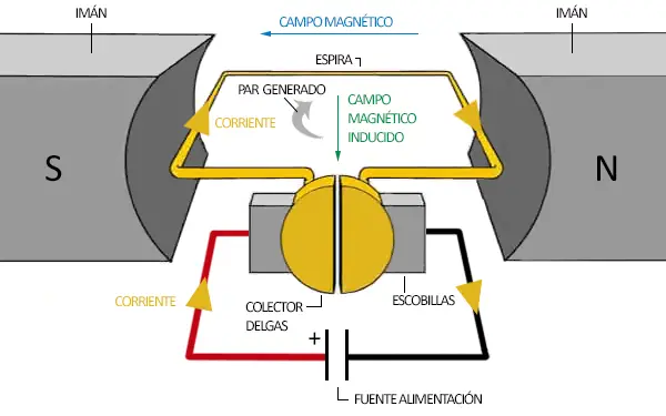
Inside it, we place a coil and pass an electric current, which generates a magnetic field. The angular phase difference between the two magnetic fields generates a torque, causing the rotor to turn until the two magnetic fields align.
When both magnetic fields were aligned, the motor would stop. To make the motor turn continuously, we are going to reverse one of the magnetic fields, for which we need to reverse the direction of the current flowing through the coil.
To do this, the contacts that power the coil in DC motors are made of a split ring that slides over electrical contacts that rub against it, transmitting electricity. The split ring attached to the shaft is called a commutator, while the sliding contacts are called brushes.
After a certain angle, the brushes will move from one segment to the next. This causes the current in the coil to reverse. In this way, the brush-commutator assembly acts as a mechanical inverter and allows the motor to rotate continuously.
The advantage of this system is that the synchronization is always perfect regardless of the speed and torque exerted, since it is the motor’s own rotation angle that marks the current reversal. The downside is that friction causes a loss of efficiency and reduces the motor’s lifespan.
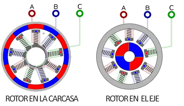
There are other arrangements of direct current motors. Sometimes the stator’s magnetic field is generated by a coil instead of a permanent magnet. Other times, the positions of the elements are swapped between rotor and stator. It is also possible for the stator to be the motor shaft, and the rotor to be the motor casing.
In any of these variations, the motor’s operation is the same: to have two misaligned magnetic fields so they rotate to align, and to use a commutator and brush system to reverse the magnetic field of one of them when they align.
In a real motor, of course, there is not just one coil, but coils made up of multiple turns. Furthermore, there are often more than one coil, which increases the motor’s power without increasing its size.
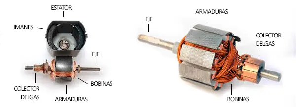
On the other hand, the coils are wound around ferromagnetic cores, called armatures, which increases the motor’s power and reduces losses due to magnetic dispersion. The armatures are composed of insulated laminations to reduce losses from induced eddy currents.
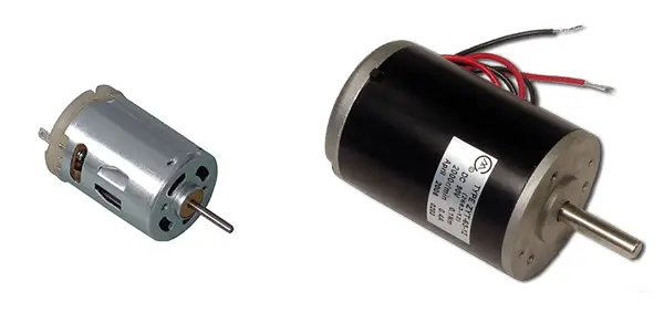
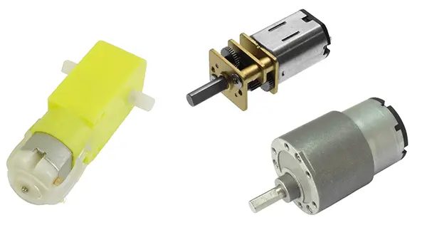
Direct current motors are available in different nominal voltages, with 6V, 12V, and 24V being common. In terms of power, we find motors of all sizes, from just a few millimeters long to much larger.
The motors have high rotation speeds and low torque. We can use Arduino’s PWM outputs to control the speed, but this will maintain the maximum available torque. Another option is to use an external or integrated gearbox (see below “geared down motors”) which reduces speed while increasing torque and precision.
To control a direct current motor, we will need an amplification stage, such as a BJT transistor or a MOSFET transistor. If we also want to be able to reverse the direction of rotation, we will need an H-bridge controller. Although the most convenient option is to use a controller like the L298N or the improved version TB6612FNG, which handles the necessary high currents and incorporates protections against induced voltages.
DC motors have poor position control and poor speed control. Their behavior is highly non-linear and depends heavily on the load they bear. For this reason, they are often used with an encoder that allows knowing the shaft position. Some DC motor models even integrate an encoder internally.
More information about controlling direct current motors at
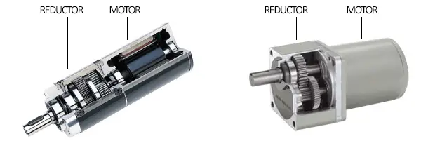
Geared Down Motors
A geared down motor is a direct current motor that incorporates an internal gearbox. This increases the motor’s torque and reduces its speed. Common rotation speeds are 60, 120, 240, and 480 rpm, among others.
It is common for some geared down motors to incorporate an internal encoder. This encoder is usually applied on the high-speed side, so the precision is superior to adding an encoder coupled to the shaft.
Geared down motors are common for driving robot and vehicle wheels.
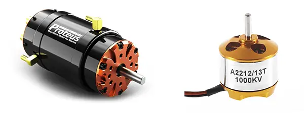
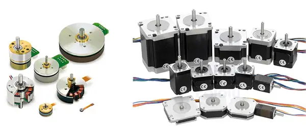
Brushless Motors
Brushless motors (BLDC) are another variation of direct current motors that dispenses with brushes as the current rectification system. Instead, they use electronics to perform the magnetic field commutation.
Since they have no brushes, brushless motors have higher speeds, lower weight, and greater durability than traditional DC motors.
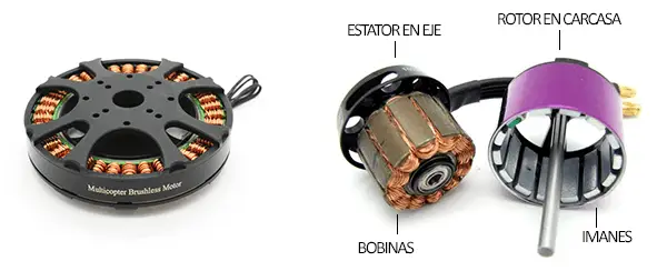
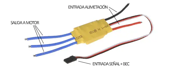
Some small brushless motors incorporate the necessary electronics for their operation internally. However, larger motors require an external controller, called an ESC (Electronic Speed Controller). Some ESCs also have a BEC (Battery Elimination Circuit) function, which consists of a regulated 5V output, typically 1-3A, to power other electronics.
Brushless motors are widely used in quadcopters and other aerial vehicles. They are also used in boat propellers, fans, and, in general, in applications that require high rotation speed.
Servo Motors
Servos are another very common actuator in robotics projects. A servo receives a pulsed signal generated by a processor, which transmits the desired position, and the servo autonomously positions itself at that position.
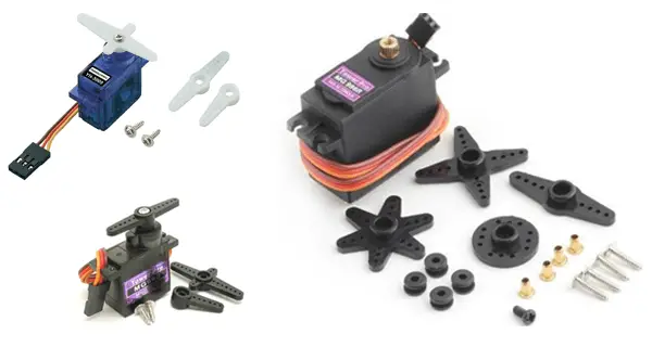
A servo cannot make a full rotation, its typical range being 180º. In return, they provide total control over position and rotation with high precision, and are very easy to use.
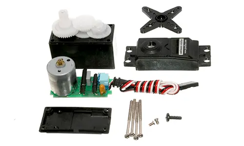
Internally, a servo consists of a DC motor coupled to a gearbox, along with a controller that positions the shaft at the indicated angle. Being coupled to a gearbox, a servo’s speed is relatively low and they provide high torque.
Servos are widely used in robotics projects, such as robotic arms, hexapods, or bipedal robots. They can also be used in turrets, or to position a sensor, or a laser, for example.
More information about using servos with Arduino at
Continuous Rotation Servo Motors
A continuous rotation servo is a variant of a conventional servo, in which the electronics are modified so that the signal controls the speed instead of the position.
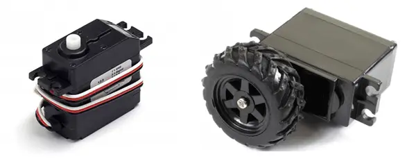
As their name suggests, continuous rotation servos are capable of making a full rotation, behaving similarly to a DC motor, with integrated speed control. In return, we lose position control, so if we want to control it, we will need to add an encoder.
However, continuous rotation servos do not offer precise control over rotation speed because, in general, they do not have a linear response to the received signal. To have good control, we will have to calibrate the servo and adjust the sent signal, or again add an encoder.
More information about using continuous rotation servos with Arduino at Control a continuous rotation servo with Arduino
Stepper Motors
Stepper motors (also called steppers) are another type of motor widely used in robotics. In this type of motor, the shaft rotates a fixed angle called a “step” when instructed by a processor. The step varies by motor model, with common values being 1.8º (200 steps per revolution) and 3.75º (96 steps per revolution).
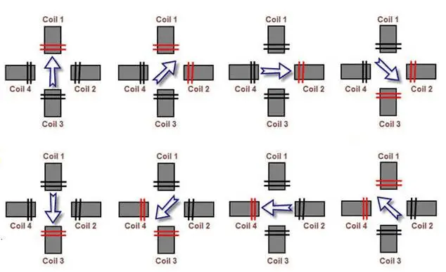
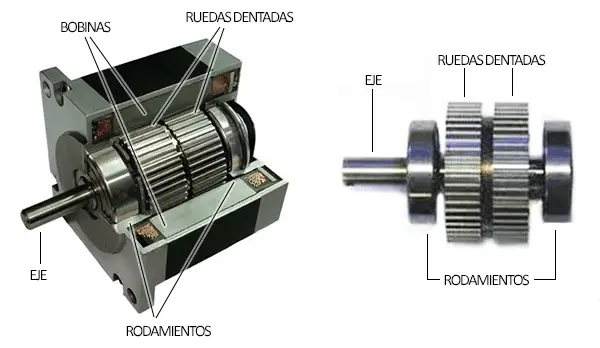
Broadly speaking, a stepper motor consists of a stator with two coils offset by 90º and a rotor formed by a permanent magnet installed solidly on the shaft.
By applying an appropriate activation sequence to the coils, we can make the magnet orient progressively, until it makes a full rotation. If the sequence is incorrect, the motor will not move.
For this reason, a stepper motor absolutely needs a processor to function; it is not possible to activate them simply by connecting them to power.
In the real world, a motor that can only take 90º steps would not be very useful. To achieve a smaller step, we could think of adding multiple coils, but that would add weight without increasing power.
To achieve the effect of having “multiple coils,” the variation of magnetic reluctance is used. A toothed wheel is attached to the shaft, with a number of teeth such that the next tooth is offset relative to the remaining coils.
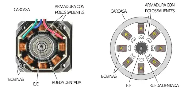
When a coil is activated, the toothed wheel is attracted by the generated magnetic field so that the rotor turns to minimize the distance of the magnetic circuit.
In the image above, it may seem like there are “8 coils” but in reality, there are only 2 coils A and B, each with 4 poles. When a coil is activated, all poles work together.
There are unipolar or bipolar motors. The difference is that unipolar motors have both coils split in two, for which they have an additional terminal on each phase.
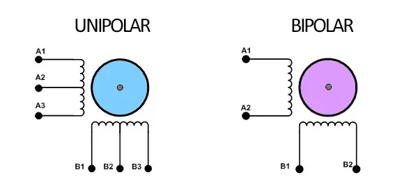
Bipolar motors have four conductors, and unipolar motors have five or six (depending on whether the center tap is common for both coils).
Unipolar motors can be simpler to operate, since if we use only half a coil, we can avoid having to reverse the direction of current flow through the coil. On the other hand, if we operate in unipolar mode, we will have less power, since we are only using half a coil to make the motor work.
With current electronics and existing controllers, reversing the current direction is not a difficulty, so in general we will prefer bipolar motors. However, any unipolar motor can be operated as bipolar, simply by leaving the center tap unconnected.
Stepper motors have total position and speed control. The precision depends on the motor’s step and the control mode used. Thus, we can control the stepper motor with activation in four steps, or in eight. By activating in eight steps, we will achieve half the nominal step. On the other hand, some controllers have microstepping, a technique that consists of varying the intensity supplied to each of the coils. In this way, step precisions of 1/16 to 1/32 of the motor’s nominal step are achieved. The maximum torque generated by a stepper motor is intermediate, being, in general, higher than that of a DC or brushless motor, but lower than a DC motor with a gearbox or a servo.
The maximum speed is also intermediate, although it is difficult to determine because it depends on the motor’s internal parameters and operating conditions. As an example, the typical maximum speed of a NEMA 17 motor is around 600 rpm, reaching up to 4800 rpm in some models.
In the past, we could recycle stepper motors from machines like scanners and printers, but they have progressively been replaced by DC motors.
Stepper motors are widely used in electronics projects, such as 3D printers and CNC machines. They are also suitable for heavy vehicles, or those requiring great synchronization between wheels, such as vehicles with omni wheels or mecanum wheels.
More information about controlling bipolar stepper motors with Arduino at Stepper motors with Arduino and A4988 or DRV8825 driver
28BYJ-48 Stepper Motor
The 28BYJ-48 motor is a small, low-cost stepper motor. Electrically, it is a low-power motor, powered at 5V, with a step of 5.624 (64 steps). But it has the peculiarity of incorporating an internal 1/64 gearbox.
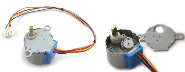
This means the overall precision is less than 0.087º (4096 steps) and a torque of 0.3kg/cm. It can operate at a maximum frequency of 100Hz, so the maximum speed is 1 revolution every 40 seconds.
Don’t let its low price and modest characteristics make you discard this motor. Its high precision and low price make it interesting for precision applications, such as rotating a 3D scanning platform, or aiming a sensor or a laser.
It can even be a viable substitute for servos in some articulated robots that require high precision and low speed, such as drawing articulated robots.
More information at 28BYJ-48 stepper motor with Arduino and ULN2003 driver
Summary Table
The information above is summarized in the following table. Of course, it will depend on the particular model of each chosen motor, but broadly speaking and as a summary,
| Characteristics | Control (*) | |||
|---|---|---|---|---|
| Speed | Force/Torque | Position | Speed | |
| DC Motor | ▲High | ▼Low | ▼Poor | ▼Poor |
| Geared Down DC Motor | – Medium | ▲High | ▼Poor | ▼Poor |
| Brushless Motor | ▲▲Very High | ▼Low | ▼Poor | – Medium |
| Servo | ▼Low | ▲High | ▲▲Absolute | ▲▲Absolute |
| Continuous Rotation Servo | ▼Low | ▲High | ▼Poor | – Medium |
| Stepper Motor | - Medium | - Medium | ▲▲Absolute | ▲▲Absolute |
| 28BYJ-48 Stepper Motor | ▼▼Very Low | Low | ▲▲Absolute | ▲▲Absolute |
Conclusions
DC motors are a winning option for vehicles with wheels or tracks. To have adequate speed control, we will need to add encoders.
An alternative is to use continuous rotation servos, which provide simple speed control. They are also a suitable option for robots with more than two motors, such as robots with omniwheels or mecanum wheels.
Conventional servos are the standout option for jointed robots such as robotic arms, hexapods, and bipeds.
Brushless motors are more suitable for projects that require high speeds with low weight, such as quadcopters and other aerial or maritime vehicles.
Finally, stepper motors are suitable for applications with high precision in speed and position, such as 3D printers, CNC machines, and advanced vehicles.