In the previous post we started the project of assembling a servo turret, a 2-DOF mobile platform that allows us to orient a sensor or actuator, presenting the budget.
In this post we will focus on the assembly and electrical diagram of this small project, it is very useful in multiple situations.
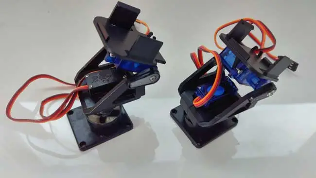
Assembly of the servo turret
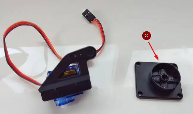
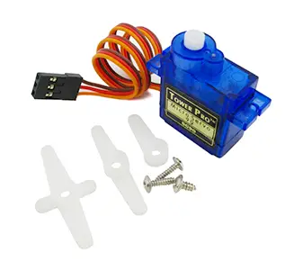
Plastic servo turret
Well, it’s not exactly the most difficult assembly in the world. Basically, the servos will act as the body and joints.
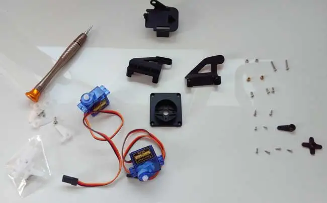
To connect the servos with the turret pieces, we will use the servo horns (the accessories that are placed on the servo shaft).
In some cases, when buying the turret, we are given servo horns that have the appropriate dimensions to mount on the turret. If our turret does not have them, we will have to use the ones that come with the servo.
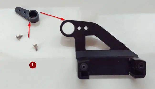
Let’s see the necessary steps to assemble the turret in the correct order. If you skip a step, you will find yourself disassembling a part :).
- Screw the servo horn that will hold the second servo.
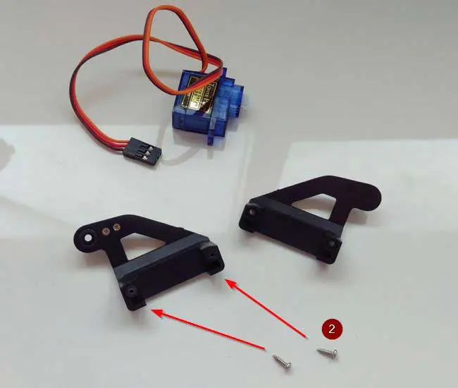
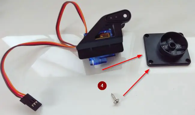
 2. Screw the top part of the turret around one of the servos.
 3. Screw the lower cross to the base of the turret.
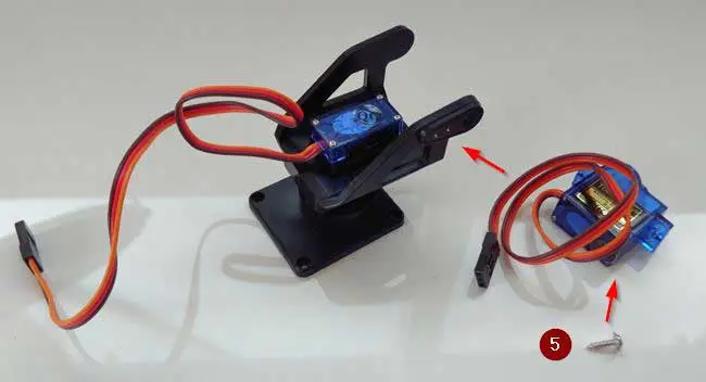
 4. Join the middle part of the turret to the base, screwing the servo to the lower cross.
 5. Fix the second servo to the body of the turret, using the servo horn placed in step 1.
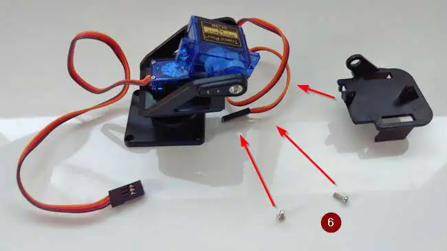
 6. Screw the top part of the turret, using the side fixing holes of the second servo.
So much for the theory. Now, the reality/problems you will encounter. The servo horns that come with the turret sometimes fit too tightly on the servo shaft, and you will have to apply a little force, being very careful not to break the servo.
On the other hand, if the turret we bought does not come with servo horns, we will have to use the ones that come with the servo. In this case, they will not fit perfectly on the turret. In particular:
- In step 1, you may have to cut the tip of the servo horn a little.
- In step 4, the cross will not fit in most cases. You will have to cut and, in many cases, glue (and even use a lot of glue).
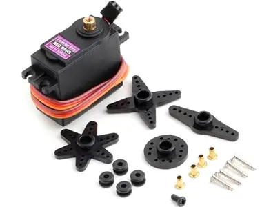
Metal servo turret
In the case of a metal servo
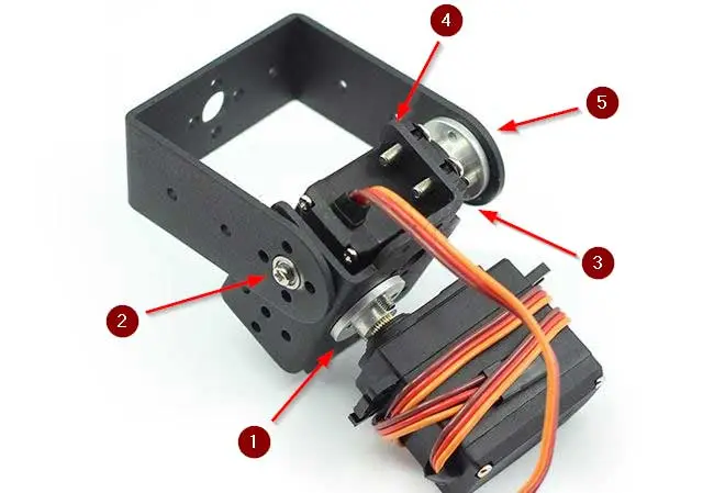 1. Attach the bottom bracket to the first servo using the circular servo horn. 2. Screw both brackets with the piece that forms the joint. 3. Screw the servo horn to the second servo. 4. Slide the second servo to the lower bracket and screw them together. 5. Screw the horn of the second servo to the upper bracket
Calibrating the servos
On the other hand, it is important to calibrate the servos. That is, we have to make the servo’s range of motion match what we want, for example, for the turret to move from -90 to 90 degrees.
First, it is convenient to set the servos to 0 degrees before assembly. Even so, it is almost inevitable that they will move, even slightly, when assembling. Therefore, once assembled, you will have to set them back to zero and adjust them, and finally finish the fine adjustment in the code.
A quite tedious process that you must get used to because it will be a constant in all projects with servos.
Electrical diagram
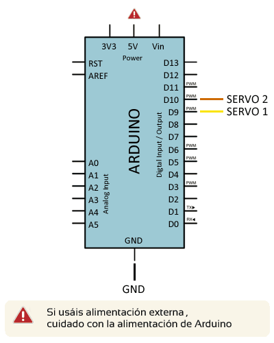
The electrical diagram is very simple, we only have to control the two servos as we saw in the post Controlling a servo with Arduino. Therefore, we only need two digital outputs of Arduino (for example, 8 and 9)
Therefore, the connection seen from Arduino is as follows
And the connection of the servos, to which we are more than accustomed, is as follows
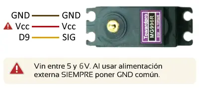
For power, we will need to use a common GND, and power the servos with a voltage of 5-6V.
In the case of a small turret with SG-90 type motors, the Arduino regulator is sufficient to move both servos (although it is not a bad idea if you have independent power).
In the case of the metal turret with MG996R type motors, it will consume too much to move them with Arduino, so we will have to use an external power source.
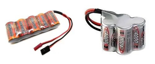
For power with batteries, my favorite option is a 5-cell NiMh battery, which provides us with 6V, which is a very suitable voltage to handle servos.
Another option is to use a regulated power source (for example, a power bank for charging cell phones) that provides 5V, and use it for Arduino and for the Servos.
However, LiPo batteries give us between 7.4 to 8.2V, which is too much for the servos. In this case, we will have to install a voltage regulator.
More about batteries in the post Options for powering Arduino with batteries
Finally, after assembly, you will probably want to do something so that you don’t have tangled cables. We have several options, from giving a little touch of glue to the cables at certain points, being careful not to damage them, or attaching some type of plastic tie or fastener that serves as a cable guide while the servo moves.
And that’s it! You just need to add the accessories you want (sensors, etc) to the turret. In the next post, we will see code examples for controlling the turret.
Download the code
All the code from this post is available for download on Github.