What is a TMC2100, TMC2130, or TMC2208?
The drivers in the TMC2xxx series are ultra-silent stepper motor drivers manufactured by the company TRINAMICs.
The TMC2xxx drivers are designed to have a pinout scheme compatible with the popular A4988 and DRV8825 drivers. Therefore, it is possible to replace one with the other, taking into account the considerations that we will see in the rest of the entry.
The TMC2xxx drivers feature functions to detect rapid load changes in the motor. They also detect when the motor is stopped to reduce the current and thus reduce power consumption and heat. In addition, the TCM2xxx drivers incorporate safety and fault protection functions, such as protection against overtemperature, short circuits, and low voltage.
In general, the TMC2xxx controllers have two main operating modes:
- The high power mode (spreadCycle) suitable for high speeds or heavy loads.
- The quiet mode (stealthChop) that reduces noise during low speeds.
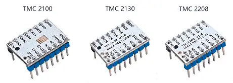
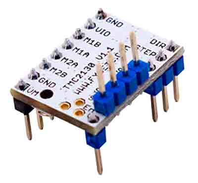
The TMC2xxx series is composed of a large number of controller models, among which the TMC2100, TMC2130, and TMC2208 models are very common. They are physically almost indistinguishable, unless we read the model on the board or the pin labels.
The TMC2100 controller is an ultra-silent controller that allows control with up to 1.2A (RMS) of nominal current and up to 2.0A peak. The configuration is done through pins, and its use is similar to the A4988 and DRV8825.
The TMC2130 controller is a more advanced version that can be configured and controlled via SPI. It also incorporates advanced functions such as detecting the force exerted by the motor, which, among other things, avoids the need for endstop switches.
The TMC2208 controller is controlled and configured via UART and incorporates an improved quiet mode (stealthChop2) that works better at higher accelerations. In addition, the resistance is lower, resulting in lower heat dissipation. It is a driver especially designed for 3D printers, although it lacks some advanced features compared to the TMC2130.
Trinamic TMC2xxx controllers are high-tech drivers that can be included in any project that handles stepper motors. One of the prominent uses is upgrading the drivers of 3D printers, a highly recommended improvement that makes them almost completely silent (except for the fans).
Price
Trinamic drivers are slightly more expensive than the usual A4988 and DRV8825 controllers, in exchange for providing much superior features.
We can find the TMC2100 for about 5.75, or in batches of 5 for about 28€ (5.6€ / unit). The TMC2130 is slightly more expensive, about 7.30€ per unit, or 5 for about 33€ (5.66€ / unit). Finally, the TMC2208 costs about 5.4€, or 5 for about 20.50€ (4.08€ / unit).
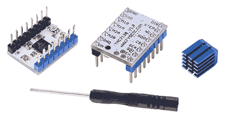
Finally, when buying one of these drivers, they will usually send us a screwdriver with a plastic tip. It is to turn the potentiometer on the board safely. Do not use this screwdriver for any other purpose, or you will easily damage it.
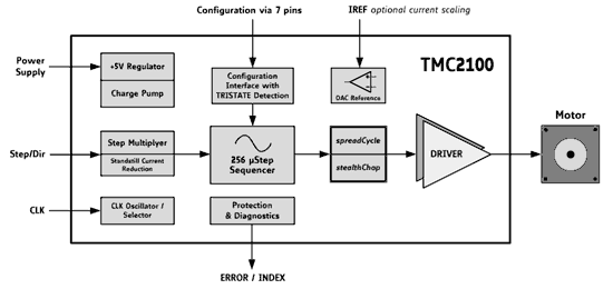
How Do TMC2xxx Work?
The Trinamics TCM2xxx drivers are much more than controllers, they are actually very advanced devices with their own computing capabilities, and a large number of components, options, and possible configurations.
The silent behavior, one of the most remarkable features of the TMC2xxx, is achieved through a highly precise chopper algorithm that achieves inaudible operation both during movement and at stops.
It is impossible to analyze in detail all the details of these controllers, which also have differences between them. In the rest of this section, we will limit ourselves to seeing the most remarkable ones.
Differences Between TMC2xxx Models
We start with a table summarizing the main features and differences between the TMC2100, TMC2130, and TMC2208.
| Name | TMC2100 | TMC2130 | TMC2208 |
|---|---|---|---|
| Interface (Step/Dir) | Pins | Pins or SPI | Pins or UART |
| Configuration | Pins | Pins or SPI | Pins or UART |
| Native MicroSteps | 1…16 | 1…256 | 1…256 |
| Interpolated MicroSteps | 1…256 | 1…256 | 1…256 |
| Phase Current, RMS | 1.2A | 1.2A | 1.2A |
| Phase Current, Peak | 2.5A | 2.5A | 2A |
| Motor Voltage (Vm) | 4.75…46V | 5.5…46V | 5.5…36V |
| Vm Always Required | No | Yes | Yes |
| Internal Regulator | No | Yes | Yes |
| Logic Voltage | 5V | 3-5V | 3-5V |
| RDSon | > 0.5 Ohm | > 0.5 Ohm | < 0.3 Ohm |
| StealthChop™ | v1 | v1 | v2 |
| SpreadCycle™ | X | X | X |
| MicroPlyer™ | X | X | X |
| StallGuard™ | v1 | v2 | v2 |
| Short Detection | X | ||
| CoolStep™ | X | ||
| Passive Braking | X |
Functions of TMC2xxx
Here is an explanation of some of the terms listed in the previous table that are necessary to understand the operation and configuration of the TMC2xxx.
- stealthChop™, high-precision silent operation mode.
- stealthChop2™, an evolution of the previous one that improves operation at high speeds and with the motor stopped, and improves torque.
- spreadCycle™, high-power operation mode (not so quiet).
- stallGuard, reduces the current when the motor is stopped, reducing consumption and heat.
- stallGuard2™, an improved version of the previous one, which allows detecting when the motor makes an effort. It allows eliminating the endstops.
- microPlyer™, 256 microstep interpolator that improves the smoothness of normal microsteps.
- coolStep™, adaptive current control that reduces power consumption.
- dcStep, load-dependent speed control. The motor moves at the highest possible speed without losing steps.
- Hybrid mode, it is a TMC2xxx operating mode, not the microcontroller controlling it. It consists of using stealthChop for slow/medium movements, and switching to spreadCycle for fast movements.
Modes of Use of TMC2xxx
The TMC2xxx have three modes of use and configuration. It is essential to understand the differences in order to use them in our projects.
Mode 1 (Legacy):
The “legacy” mode is the simplest mode to use. Basically, the communication between the microprocessor and the driver is discarded, allowing it to be used as a direct replacement for A4988 and DRV8825 drivers.
Since the TMC2100 does not have communication, it is the only mode available. However, both the TMC2130 (SPI) and the TMC2208 (UART) can be configured as Legacy with some small solder points on the board.
Mode 2 (OTP):
Another option is to configure the drivers (TMC2130 and TMC2208) using a TTL serial converter and overwrite the configuration we want in configuration registers in a one-time programmable memory (OTP).
The downside is that it can only be done once (or rather, the bits can only be changed to 1, they cannot be changed back to 0), so the driver will be permanently configured.
Therefore, it is not an interesting option as it eliminates the advantage of communication with the microprocessor. It only makes sense in truly stand-alone applications, where we want to fix the configuration.
Mode 3 (SPI or UART):
The best option is to use the available communication, SPI in the case of the TMC2130 (SPI) and UART in the TMC2208, to dynamically configure and control the driver from a microprocessor. This allows us to obtain the status and configuration details of the drivers and change their configuration “on the fly”.
The downside is that, logically, we must have a microprocessor and add the necessary wiring for communication with the driver (in the case of the TMC2130 SPI, it can be up to 5 wires). In addition, if we are replacing A4988 or DRV82825 drivers in an existing setup (for example, your printer with RAMPS), it may be a problem to have the necessary connections.
Connection and Mounting of TMC2xxx
The modules with TMC2xxx are mounted with the chip facing down. The chips have a thermal pad soldered to the PCB, so the thermal resistance is better than placing the heat sink directly on the chip. In general, we will need a heat sink in any case, and depending on the intensity we handle, a fan (which, in any case, is highly recommended).
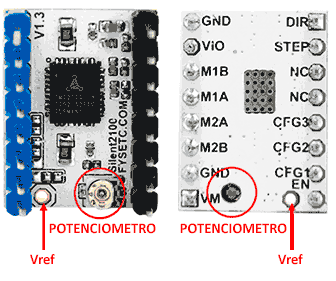
When replacing A4988 and DRV8825 drivers, check that the orientation of the TMC2xxx is correct. The position of the potentiometer on some boards may be in a different position and lead us to error. Pay attention only to the pin labels and do not trust any other reference.
However, if we are going to mount the TMC2xxx on an existing setup, it is possible that the connections on the TMC2xxx pins interfere (for example, when mounting it on a board like RAMPS). Therefore, it is common to have to mount some of the terminals “upwards”.
Maximum Current in TMC2xxx
Similar to the A4988 and DRV8825 drivers, the TCM2xxx have a potentiometer that allows adjusting the maximum power delivered to the motor. To adjust the maximum current, we will measure the voltage between the Vref pin and GND (0 to 2.5V) and adjust the potentiometer.
Also, like the A4988 and DRV8825, the current delivered to the motor can be calculated as an expression between the reference voltage (Vref) and GND, which includes the RSense resistance on the board.
The RSense on many boards is 0.11, in which case the above expression is simply reduced to:
However, in some models, the RSense is 0.22 or 0.1. Therefore, verify the value of your RSense resistance before making the calculation.
On the other hand, when talking about the TCM2xxx drivers, the current RMS is normally referred to, instead of peak voltage as in the A4988 and DRV8825. In the case of talking about Irms, the expression would be:
Remember, Ipico = IRmx * 1.414 or, equivalently, IRms = IPico * 0.707.
Here is a table with some of the relationships to make the calculation easier:
| Vref | Irms | Ipico |
|---|---|---|
| 1.4 | 0.991 | 1.4 |
| 1.3 | 0.920 | 1.3 |
| 1.2 | 0.850 | 1.2 |
| 1.1 | 0.779 | 1.1 |
| 1 | 0.708 | 1.0 |
| 0.9 | 0.637 | 0.9 |
| 0.8 | 0.566 | 0.8 |
| 0.7 | 0.496 | 0.7 |
| 0.6 | 0.425 | 0.6 |
| 0.7 | 0.496 | 0.7 |
The maximum is 1.25A rms, which is equivalent to 1.77A peak. For a NEMA 17 motor (as commonly used in 3D printers), the usual nominal current range is in the range of 0.5A-0.8A RMS, which translates into a Vref voltage range of 0.7V to 1.1V.
When adjusting the intensity, it is not advisable to adjust the maximum intensity to the maximum of the motor. Start by using low values (0.5A, Vref=0.7V) and if you see that it loses steps, increase the current in steps of 0.1A until it works correctly.
Trinamic drivers incorporate protection against overtemperature if the chip exceeds 150ºC. However, it is advisable to have good cooling (heat sink) and for Vref above 0.55V, it is necessary to add a fan.
How to Turn Off TMC2xxx
The A4988 and DRV8825 drivers were already very sensitive, especially to disconnecting the motor when the driver had current. Trinamic sensors are even more sensitive to induced currents (EM) by the motor. To avoid damaging the drivers or even the microprocessor, it is essential to have a series of considerations when turning off the assembly.
The first rule is, similarly, not to disconnect the motor while the driver is powered. Another golden rule with the TMC2xxx drivers is not to turn off the assembly while a motor is moving.
However, an ‘emergency stop’ can be performed by setting the EN pin to HIGH, which essentially disconnects the driver’s electronics from the motor.
Turning Off Drivers with 3-5V Variable Power Supply
Drivers with a 3-5V logic supply (TMC2130 and TMC2208) have additional considerations. These drivers incorporate an internal voltage regulator, which powers the driver’s logic from the voltage applied to the motor, Vm.
The existence of this internal regulator, in addition to involving additional power losses that must be dissipated by the driver, conditions the power-on and power-off sequence.
In drivers with 3-5V power supply the Vm current must always be present, that is, connect Vm before turning on the driver electronics, and disconnect Vm after turning off the driver electronics. Otherwise, the EM may damage the driver.
On the other hand, we cannot move the motors “by hand” quickly, or we can damage the driver (in any case, moving the motor by hand is something you should always avoid).
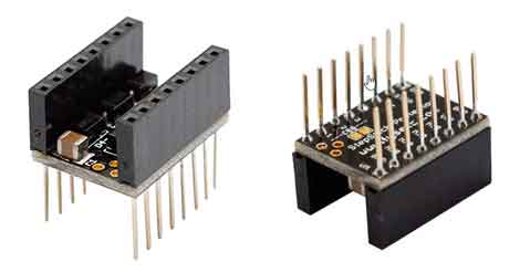
To avoid this circumstance, we can add a protection base to the TMC2130 and TMC2208, which incorporates flyback Schottky diodes that protect the driver from EM.
If you use TMC2130 or TMC2208 drivers in a 3D printer, and you connect the USB, make sure your printer is turned on or you will damage the drivers.
Mounting Scheme
TMC2100
The TMC2100 driver does not have SPI or UART communication, so the only available mode is Legacy. Therefore, the connection is similar to that of an A4988 or DRV8825.
The TMC2100 configuration is done by connecting the corresponding configuration pins. The pins can be connected to any of the 3 states, LOW (GND), HIGH (VIO), or Open (unconnected).
| CFG1 | CFG2 | Steps | Interpolation | Mode | | --- | --- | --- | --- | | GND | GND | 1 (full step) | none | spreadCycle | | VCC | GND | 2 (half-step) | none | spreadCycle | | open | GND | 2 (half-step) | 256 µ-steps | spreadCycle | | GND | VCC | 4 (quarter-step) | none | spreadCycle | | VCC | VCC | 16 µ-steps | none | spreadCycle | | open | VCC | 4 (quarter-step) | 256 µ-steps | spreadCycle | | GND | open | 16 µ-steps | 256 µ-steps | spreadCycle | | VCC | open | 4 (quarter-step) | 256 µ-steps | stealthChop | | open | open | 16 µ-steps | 256 µ-steps | stealthChop |
Alternatively, we can also solder some small jumpers located on the board.
Therefore, the connection of the TMC2100 would be as follows:
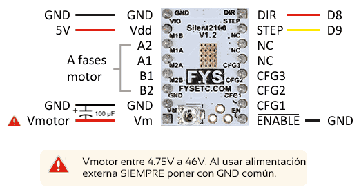
While the connection, seen from the processor, would be.
TMC2130
By default, the TMC2130 comes configured to be used in Legacy mode, serving as an almost direct replacement for the A4988 and DRV8825 drivers. Therefore, the scheme and connection would be similar to the TMC2100, and the configuration will be carried out through the configuration pins.
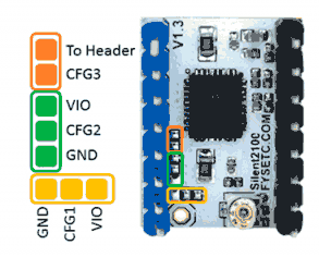
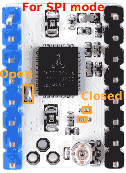
However, if we want to take full advantage of the TMC2130, we will want to activate SPI communication for driver control and configuration. To do this, we must solder the jumpers of the TMC2130 as shown in the following image.
With the SPI communication activated, we must connect the SPI bus pins, so the connection of the TMC2130 would be as follows:
| Microprocessor | Driver |
|---|---|
| SCK | SCK |
| MOSI | SDI |
| MISO | SDO |
| CS | CS |
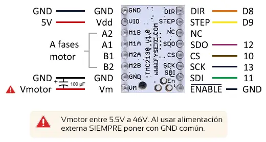
While the connection, seen from the processor, would be.
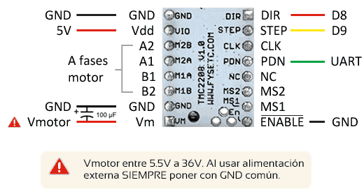
TMC2208
By default, the TMC2208 comes configured to be used in Legacy mode, serving as an almost direct replacement for the A4988 and DRV8825 drivers. Therefore, the scheme and connection would be similar to the TMC2100, and the configuration will be carried out through the configuration pins.
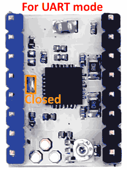
However, if we want to take full advantage of the TMC2208, we will want to activate UART communication for driver control and configuration. To do this, we must solder a jumper of the TMC2208 as shown in the following image.
| Microprocessor | Driver |
|---|---|
| RX | PD_UART |
| TX (1kohm) | PD_UART |
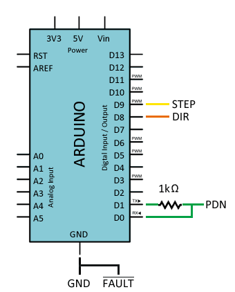
With the UART communication activated, we must connect the corresponding pins. The TMC2208 uses a special UART protocol that allows using a single pin (PDN) for transmitting and receiving. To make it work, we must interpose a 1kOhm resistor between the TX pin and the PDN pin. Therefore, the connection of the TMC2208 would be as follows:
While the connection, seen from the processor, would be.
Code examples
The code is independent of the driver, and the same as we saw in the entry of A4988 and DRV8825. Therefore, we will use the same code as the base, which we copy below. However, we will also see common cases for each of the TMC2100, TMC2130, and TMC2208 drivers.
It should be noted that in the TCM2xxx drivers, the direction pin is inverted, that is, it is activated when it goes to LOW. Therefore, the direction of rotation will be opposite to what we will have with an A4988 or DRV8825 driver.
const int dirPin = 8;
const int stepPin = 9;

const int steps = 200;
int stepDelay;

void setup() {
  // Mark the pins as output
  pinMode(dirPin, OUTPUT);
  pinMode(stepPin, OUTPUT);
}

void loop() {
  //Activate a direction and set the speed with stepDelay
  digitalWrite(dirPin, HIGH);
  stepDelay = 250;
  // Rotate 200 pulses to make a complete turn
  for (int x = 0; x < 200; x++) {
    digitalWrite(stepPin, HIGH);
    delayMicroseconds(stepDelay);
    digitalWrite(stepPin, LOW);
    delayMicroseconds(stepDelay);
  }
  delay(1000);

  //Change the direction and increase the speed
  digitalWrite(dirPin, LOW);
  stepDelay = 150;
  // Rotate 400 pulses to make two complete turns
  for (int x = 0; x < 400; x++) {
    digitalWrite(stepPin, HIGH);
    delayMicroseconds(stepDelay);
    digitalWrite(stepPin, LOW);
    delayMicroseconds(stepDelay);
  }
  delay(1000);
}
TMC2100
The TMC2100 only has Legacy mode, so the code is what we saw in the previous case.
TMC2130
The TMC2130 has Legacy mode, for which we will use the previous example. But if we want to get the most out of it, we will use SPI communication to control and configure the TMC2130. To do this, we will use the library available at https://github.com/teemuatlut/TMC2130Stepper.
The library incorporates examples and extensive documentation on its use. However, here is the example code of this post adapted to show the use of the TMC2130 by SPI.
const int enPin = 16;
const int dirPin = 19;
const int stepPin = 18;
const int csPin = 17;

const int steps = 200;
int stepDelay;

#include <TMC2130Stepper.h>
TMC2130Stepper TMC2130 = TMC2130Stepper(enPin, dirPin, stepPin, csPin);

void setup() {
  Serial.begin(9600);

  pinMode(stepPin, OUTPUT);

  TMC2130.begin(); // Initialize TMC2130
  TMC2130.SilentStepStick2130(600); // Set current to 600mA
  TMC2130.stealthChop(1); // Activate silent mode
}

void loop() {
  //Activate a direction and set the speed with stepDelay
  driver.shaft(true);
  stepDelay = 250;
  // Rotate 200 pulses to make a complete turn
  for (int x = 0; x < steps; x++) {
    digitalWrite(stepPin, HIGH);
    delayMicroseconds(stepDelay);
    digitalWrite(stepPin, LOW);
    delayMicroseconds(stepDelay);
  }
  delay(1000);

  driver.shaft(false);
  stepDelay = 150;
  // Rotate 400 pulses to make two complete turns
  for (int x = 0; x < steps * 2; x++) {
    digitalWrite(stepPin, HIGH);
    delayMicroseconds(stepDelay);
    digitalWrite(stepPin, LOW);
    delayMicroseconds(stepDelay);
  }
  delay(1000);
}
TMC2208
The TMC2208 has Legacy mode, for which we will use the previous example. But if we want to get the most out of it, we will use UART communication to control and configure the TCM2208. To do this, we will use the library available at https://github.com/teemuatlut/TMC2208Stepper.
The library incorporates examples and extensive documentation on its use. However, here is the example code of this post adapted to show the use of the TMC2208 by UART.
const int stepPin = 9;

const int steps = 200;
int stepDelay;

#include <TMC2208Stepper.h>
TMC2208Stepper driver = TMC2208Stepper(&Serial);

void setup() {
  Serial.begin(9600);
  while(!Serial);

  pinMode(dirPin, OUTPUT);
  pinMode(stepPin, OUTPUT);

  driver.pdn_disable(1);  // Use PDN/UART pin for communication
  driver.I_scale_analog(0);
  driver.rms_current(500); // Set current to 500mA
  driver.toff(0x2); // Turn on friver
}

void loop() {
  //Activate a direction and set the speed with stepDelay
  driver.shaft(true);
  stepDelay = 250;
  // Rotate 200 pulses to make a complete turn
  for (int x = 0; x < steps; x++) {
    digitalWrite(stepPin, HIGH);
    delayMicroseconds(stepDelay);
    digitalWrite(stepPin, LOW);
    delayMicroseconds(stepDelay);
  }
  delay(1000);

  driver.shaft(false);
  stepDelay = 150;
  // Rotate 400 pulses to make two complete turns
  for (int x = 0; x < steps * 2; x++) {
    digitalWrite(stepPin, HIGH);
    delayMicroseconds(stepDelay);
    digitalWrite(stepPin, LOW);
    delayMicroseconds(stepDelay);
  }
  delay(1000);
}
Download the code
All the code in this post is available for download on Github. 
