
We continue with the series of PCB design posts by looking at the sizes and dimensions of SMD components we will frequently encounter.
In the previous post, we saw the common sizes for PTH components and emphasized the importance of verifying dimensions before sending a PCB for manufacturing.
In the case of SMD, sizes are much more standardized. This is logical since, in many cases, PCB assembly with SMD components is automated. Therefore, more rigor is needed than with hand-placed components.
Passive Components
This applies to resistors, inductors, and capacitors, and they are coded in standard formats according to the following table.
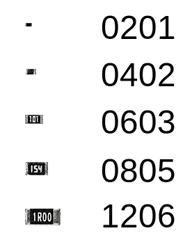
| Code | Length | Width | Height | Power |
|---|---|---|---|---|
| Imperial | mm | mm | mm | Watt |
| 0201 | 0.6 | 0.3 | 0.25 | 1/20 |
| 0402 | 1.0 | 0.5 | 0.35 | 1/16 |
| 0603 | 1.55 | 0.85 | 0.45 | 1/10 |
| 0805 | 2.0 | 1.2 | 0.45 | 1/8 |
| 1206 | 3.2 | 1.6 | 0.55 | 1/4 |
| 1210 | 3.2 | 2.5 | 0.55 | 1/2 |
Tantalum capacitors have their own dimensions. In any case, or for other types of components, again the best thing is to check the manufacturer’s Datasheet.
SMD Packages
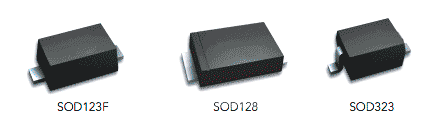
Regarding packages for integrated circuits, first, we find the SOD type (Small Outline Diode) for devices with two terminals. For example, SOD123, SOD128, and SOD323 are common.
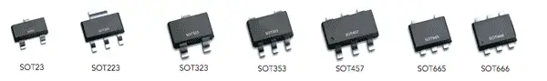
For devices with three or more terminals, the SOT package (Small-outline transistor) is common. Thus, SOT23, SOT232, among others, are frequent.
Of course, there are many more packages available. It is easy to find their dimensions online. But generally, it is simpler to start from a component with the same package that we have in the library and duplicate the component from it.
On the other hand, unlike PTH, where library components are very unreliable, in general, SMD library components tend to be more correct.
Nevertheless, the recommendation remains to validate the dimensions of any component we are going to use and that we haven’t made ourselves.
