In this post we will see how to turn on an LED using Arduino’s outputs. For this, we will see the operating principle and the necessary electrical schematic.
Of course, we can also use the content of this post to turn on an LED with any other controller, or directly by connecting it to a voltage source or battery. (The electrical schematic is the same, just replace the Arduino output with your voltage source)
In general, LEDs should always be connected through a resistor. In fact, almost any electronic element you connect should go through a resistor.
To understand the importance and role of this resistor, and to be able to calculate its value, it is necessary to understand how an LED works.
In some books or websites you will see that, sometimes, they connect the LED directly to a digital or analog output of Arduino. Although this works (we’ll see why later) it is a bad practice
What is an LED?
An LED is a light-emitting diode. That is, a particular type of diode that emits light when an electric current passes through it. Diodes (light-emitting or not) are one of the fundamental electronic devices.
Let’s remember that we differentiate between electrical and electronic devices.
- Electrical devices include resistors, capacitors, and coils, and belong to the field of electricity.
- Electronic devices arise from the use of semiconductor materials, and give rise to the field of electronics.
A diode is a junction of two semiconductor materials with different doping. This doping difference (without going into details) causes it to generate a potential barrier. This prevents current from flowing in one of the directions.
Here we have the first characteristic of diodes: they have polarity, meaning they only allow current to flow in one direction. Therefore, we must connect the voltage to the device correctly.
- The long leg must be connected to the positive voltage (anode)
- The short leg to the negative voltage (cathode)
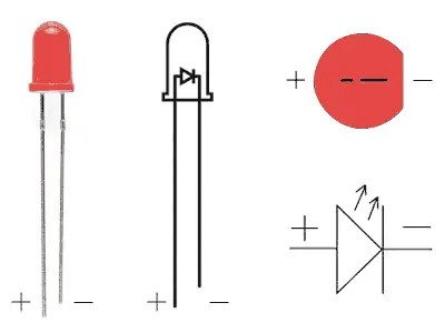
Mnemonic rule:
- The “more” longer leg is positive
- The “less” longer leg is negative
The other consequence of the potential barrier is that, even when connecting the device with the correct polarity, at low voltage the electrons still cannot pass through the device.
This happens until a certain voltage value is reached, which we call forward bias voltage (Vd), which depends on the type of diode.
Beyond this voltage, we say that the diode is biased and current can flow through it freely with almost zero resistance.
The voltage actually powering the diode is the difference between the applied voltage and the forward bias voltage of the diode.
Why we need the resistor
As we see, the moment we exceed the bias voltage, and given that the diode’s resistance is very small, a large current is generated that will destroy the diode.
For this reason, we need a resistor to limit the amount of current flowing through the diode.
That is, if we don’t put a resistor, the system only has two states.
- If we supply a voltage lower than Vd, the LED doesn’t light up ❌
- If we supply a voltage higher than Vd, the LED breaks 💥
Neither option is very good 😅. In any case, we won’t be able to make the LED light up without using a resistor of appropriate value.
Why does it work when connecting to an Arduino output?
As we mentioned earlier, sometimes you will see in Internet tutorials that some people connect an LED directly to an Arduino output, without using a resistor. Indeed, this works and the LED lights up without breaking. How is this possible?
This works because Arduino has a 20mA limitation on its outputs. This limitation prevents the LED from burning out (although it is actually behaving as if it were a short circuit). Simply put, Arduino cannot supply more current, more “juice”.
However, this is a practice that is completely discouraged for several reasons
- Firstly, because it unnecessarily strains the Arduino output, which can shorten its lifespan in the long run
- Secondly, because 20mA is, in general, too high a current for an LED
- But above all, because it’s a botch job and a total lack of electronic hygiene 😆
What types of LEDs will we use in electronics?
There is a wide range of LEDs available, from the usual low-power LEDs to the high-power LEDs used in lighting. The latter require additional power stages (drivers) to be able to turn them on from a controller.
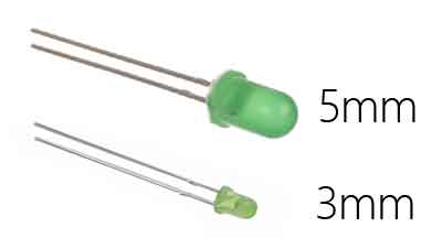
Among low-power LEDs, which are the ones we will use most frequently, the most common are the traditional 3mm or 5mm LED packages.
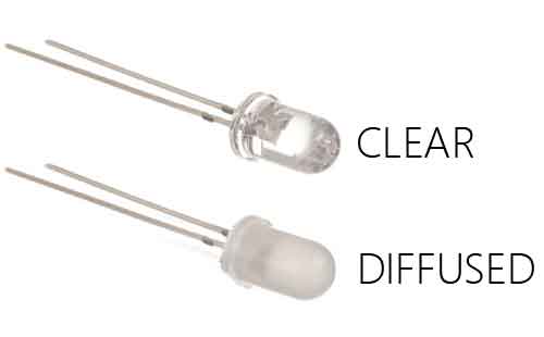
We can also find opaque (diffused) LEDs or transparent (clear) LEDs. Opaque LEDs are designed to “light up” themselves (for example, for a control panel). On the other hand, transparent LEDs are designed to illuminate an area, but not the LED itself.
Additionally, we will find LEDs with different angles. LEDs with a smaller illumination angle have a narrower beam, so they concentrate light in a narrow area. Conversely, LEDs with wider angles concentrate a lower amount of light forward, and in return illuminate a larger area.
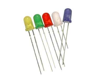
Finally, you will see that some LEDs have a colored package. This color is simply to identify the color of the light emitted by the LED without having to turn it on, but it has no influence on the color of the emitted light, which only depends on the internal construction of the LED (personally, I prefer them with an uncolored package).
How much does an LED cost?
The cost of LEDs is very similar regardless of their type and size (except, logically, high-power LEDs), although some colors may be a bit more expensive.
In general, they are really cheap devices. We can find LEDs for 1 euro cent, from international sellers on eBay or AliExpress.

Finally, note that we also have a large number of accessories available for LEDs, such as holders, threaded holders, decorative plastic caps, etc. ..and they are also very cheap, around one euro cent per unit.

Calculating the resistor value
We have said that the main thing to make an LED work is to calculate the necessary resistor value. To calculate the voltage value needed to power an LED we need to connect 3 parameters
- The supply voltage (Vcc)
- The forward bias voltage of the LED (Vd)
- The nominal current of the LED (In)
Calculating the resistor value is simple. As we said, the voltage across the LED is the difference between the applied voltage and the forward bias voltage of the LED.
Applying Ohm’s law, with the value of the LED’s nominal current
Therefore, the resistor value is
Since commercial resistors have standardized values, you won’t find a resistor with the exact value you calculated. In this case, we will choose the standardized resistor immediately higher than the calculated value, to ensure that the current is lower than the nominal one.
The supply voltage Vcc is known to us. In case of applying a power supply or a battery, Vcc is its nominal voltage. In the case of a digital or analog output of Arduino, Vcc will depend on the model we are using (5V or 3.3V) but it is also known.
Remember that even if you use a PWM analog output, the voltage delivered to the load is always Vcc. Check the post PWM Analog Outputs in Arduino if you have doubts about this.
Regarding the bias voltage and the nominal current, they depend on the materials and internal construction of the diode. In the case of conventional 3mm and 5mm LEDs, they depend mainly on the color and brightness
However, in most cases the seller themselves provides these values in the listing. In case of doubt, we should consult the LED’s Datasheet to check the nominal values.
In the following table we attach some general values of the typical forward bias voltage Vd for each color. We also give you the value of the required resistor, in Ohms, for different values of supply voltage Vcc.
| Color | Vdd | Ω (3.3V) | Ω (5V) | Ω (9V) | Ω (12V) |
|---|---|---|---|---|---|
| Infrared | 1.4V | 150 | 270 | 510 | 680 |
| Red | 1.8V | 100 | 220 | 470 | 680 |
| Orange | 2.1V | 100 | 200 | 470 | 680 |
| Yellow | 2.2V | 100 | 200 | 470 | 680 |
| Green | 3.2V | 10 | 150 | 330 | 560 |
| Blue | 3.5V | - | 100 | 330 | 560 |
| Violet | 3.6V | - | 100 | 330 | 560 |
| White | 3.8V | - | 100 | 330 | 560 |
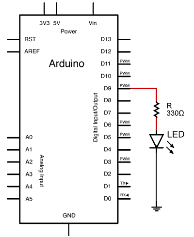
Electrical connection
The electrical connection is really simple. We simply put the previously calculated resistor in series with the LED.
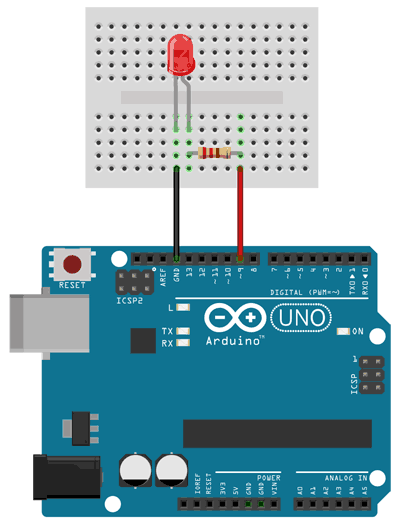
The assembly on a breadboard would look like this.
Code examples
Below are some of the codes to test turning on LEDs with our Arduinos, and the indicated assembly.
The codes are similar to those we have seen previously in the different posts on the blog, but using an external LED instead of the integrated LED on the board.
For this, we only have to replace the PIN number 13, corresponding to the integrated LED, with the PIN of the output we are going to use.
Blinking an LED
Thus, the first code is used to turn an LED on and off, as we saw in the post digital outputs in Arduino.
const int ledPIN = 9;

void setup() {
  Serial.begin(9600);    // start serial port
  pinMode(ledPIN , OUTPUT);  // define pin as output
}

void loop(){
  digitalWrite(ledPIN , HIGH);   // set the Pin to HIGH
  delay(1000);                   // wait one second
  digitalWrite(ledPIN , LOW);    // set the Pin to LOW
  delay(1000);                   // wait one second
}
Turn on N times via Serial
The following code uses digital outputs and serial communication to blink the LED the number of times we send via the serial port, as we saw in the post communication via Arduino serial port.
const int ledPIN = 9;

int option;

void setup(){
  Serial.begin(9600);
  pinMode(ledPIN , OUTPUT);
}

void loop(){
  //if there is pending information
  if (Serial.available()>0){
    //read the option
    char option = Serial.read();
    //if the option is between '1' and '9'
    if (option >= '1' && option <= '9')
    {
      //subtract the value '0' to get the sent number
      option -= '0';
      for(int i=0;i<option;i++){
         digitalWrite(ledPIN , HIGH);
         delay(100);
         digitalWrite(ledPIN , LOW);
         delay(200);
      }
    }
  }
}
Adjustable via PWM
Finally, the following code uses a PWM output to vary the intensity of the LED, as we saw in the post analog outputs in Arduino.
const int ledPIN = 5;

byte outputValue = 0;

void setup()
{
   Serial.begin(9600);         // Start serial port
   pinMode(ledPIN , OUTPUT);
}

void loop()
{
   if (Serial.available()>0)  // If there are available data
   {
      outputValue = Serial.read();  // Read the option
      if(outputValue >= '0' && outputValue <= '9')
      {
         outputValue -= '0';    // Subtract '0' to convert to a number
         outputValue *= 25;    // Multiply by 25 to scale from 0 to 250
         analogWrite(ledPIN , outputValue);
      }
   }
}
That’s all for the LED usage tutorial. It’s hard to believe how much there is to write about such a small device! We hope it’s clear how to use LEDs with or without Arduino, and we encourage you to use and test them in your experiments.
Download the code
All the code from this post is available for download on Github. 
