What is a 9-axis IMU L3GD20 + LSM303D?
The L3GD20 + LSM303D module is a 9-axis IMU that incorporates accelerometer, gyroscope, and magnetic compass functions, which we can use with a processor like Arduino to determine the sensor’s orientation.
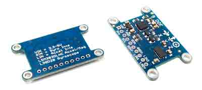
This module, as its name suggests, is made up of an integrated L3GD20 as a gyroscope, LSM303DLHC as an accelerometer and magnetic compass. Both sensors are manufactured by STMicroelectronics.
The combination of these sensors in the same module is a good quality and low-cost 9-axis IMU, which is a good replacement for other alternatives such as the popular MPU6050 and MPU9250 from InvenSense.
The range and sensitivity of the three sensors are adjustable. For the L3GD20 gyroscope, it is ±250, ±500, or ±2000 degrees per second. For the LSM303, it is ±2g, ±4g, ±6g, ±8g, ±16g for the accelerometer, and ±2, ±4, ±8, ±12 gauss for the magnetometer.
Communication with the module is done through the I2C bus, making it very easy to read from a processor like Arduino.
The integrated circuits operate at 3.3V, but the module incorporates a regulator so that the supply voltage is 2.5-5.5V. The I2C pins have level adapters, so it is safe to connect it to a 3.3V or 5V processor.
If you want to learn more about accelerometers, gyroscopes, and IMUs in Arduino, check out the series of posts How to Use an Accelerometer with Arduino, How to Use a Gyroscope with Arduino, and Measuring Tilt with IMU.
Price
We can find a 9-axis IMU L3GD20 + LSM303D for around €3.70, making it one of the best IMUs in terms of quality/price ratio.
Do not confuse with other sensors that only incorporate the L3GD20, and therefore only have 3 gyroscope axes. They cost around €2.40 and are not interesting because
There are also 10 DOF versions, which add a BMP180 as a barometer to estimate altitude, with a cost of around €4.80. I don’t particularly recommend them because the BMP180 is somewhat outdated, and for the price difference, we could buy it separately.
Assembly scheme
The connection is simple, we simply power the module from Arduino using GND and 5V and connect the SDA and SCL pins of Arduino with the corresponding pins of the sensor.
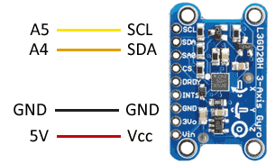
While the connection seen from the Arduino side would look like this.
On Arduino Uno, Nano, and Mini Pro, SDA is pin A4 and SCK is pin A5. For other Arduino models, check the corresponding pinout diagram.
Verify that your board is compatible with 5V before connecting it to Arduino. If not, you will have to use a level shifter.
Code examples
To read the L3GD20 + LSM303D, we will use the Adafruit libraries https://github.com/adafruit/Adafruit_L3GD20_U, https://github.com/adafruit/Adafruit_LSM303DLH_Mag, and https://github.com/adafruit/Adafruit_9DOF.
The Adafruit_9DOF library incorporates several usage examples that are worth reviewing, including an algorithm for fusing the measurement of the three sensors to achieve the module’s orientation. The following examples are modifications based on those available in the library.
#include <Wire.h>
#include <Adafruit_Sensor.h>
#include <Adafruit_LSM303_U.h>
#include <Adafruit_9DOF.h>
#include <Adafruit_L3GD20_U.h>

Adafruit_9DOF                 dof   = Adafruit_9DOF();
Adafruit_LSM303_Accel_Unified accel = Adafruit_LSM303_Accel_Unified(30301);
Adafruit_LSM303_Mag_Unified   mag   = Adafruit_LSM303_Mag_Unified(30302);

void initSensors()
{
  if(!accel.begin())
  {
    Serial.println(F("Ooops, no LSM303 detected ... Check your wiring!"));
    while(1);
  }
  if(!mag.begin())
  {
    Serial.println("Ooops, no LSM303 detected ... Check your wiring!");
    while(1);
  }
}

void setup(void)
{
  Serial.begin(115200);
  Serial.println(F("Adafruit 9 DOF Pitch/Roll/Heading Example"));
  Serial.println("");

  initSensors();  // iniciar sensor
}

void loop(void)
{
  sensors_event_t accel_event;
  sensors_event_t mag_event;
  sensors_vec_t   orientation;

  // leer el estado de los sensores
  accel.getEvent(&accel_event);
  mag.getEvent(&mag_event);

  // usar el algoritmo de fusion de la libreria para combinar las mediciones
  if (dof.fusionGetOrientation(&accel_event, &mag_event, &orientation))
  {
    /* 'orientation' should have valid .roll and .pitch fields */
    Serial.print(F("Orientation: "));
    Serial.print(orientation.roll);
    Serial.print(F(" "));
    Serial.print(orientation.pitch);
    Serial.print(F(" "));
    Serial.print(orientation.heading);
    Serial.println(F(""));
  }

  delay(100);
}
Example with RTIMULIB-Arduino
Another option for reading the sensor is to use the RTIMULIB-Arduino library, which allows you to create an AHRS (Attitude Heading Reference Systems) system and works with a wide variety of sensors. We saw how to use this library in this post.
Download the code
All the code from this post is available for download on Github. 
