
Today we are going to look at Gamma Correction, a fundamental aspect to consider when working with light sources whose intensity we want to vary using a processor like Arduino.
Let’s consider the simple case of an LED whose brightness we want to vary. Very easy, right? We simply use a PWM signal to turn the LED on and off as we saw in the last example of this post.
With this, we are turning the LED off for a certain percentage of the time, so fast that we cannot see it. The brightness, as expected, should vary in the same proportion as the time the LED is off (spoiler, it turns out it doesn’t).
If you do this very simple experiment, turning the LED on with a triangular function, you will see that the LED’s response is not linear at all. In fact, your LED will be “on almost all the time,” and the decrease and increase in brightness will occur in a very short time interval.
How can this be? What’s happening here? Ah, my friend… that’s where Gamma Correction comes in.
Gamma Correction
What’s happening is that your eye-brain is deceiving you. Your visual perception system is designed to function over a wide range and to be especially sensitive to changes in low brightness.
Even assuming your emitter’s response is linear (which, in many cases, we can assume to be true), it is your perception of light that is not linear relative to the amount of light it perceives.
That is, when your “eye-brain” sees an LED at 50% brightness (half on or half off, depending on how optimistic you are), your perception is not “it’s shining at 50%”.
Human visual perception follows an approximately power-law shape. Something similar to the orange curve in the following graph.
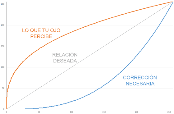
For the perception to match the value we desire (gray curve, perfectly linear), we need to apply a correction to the values we send to the light source.
This correction is what we call Gamma Correction and is represented in the previous graph by the blue curve.
Too weird? Well, that’s how your brain works.
A Numerical Example
In case it still seems too strange and to show how important the effect of Gamma Correction is, let’s try to illustrate it with a small numerical example.
Suppose you want to light an LED at 30% brightness by applying a PWM value between 0 and 255. The “logical” thing would be to apply a PWM value of 0.3 * 255, that is, around 77.
But, if we look at the perception curve (orange), with a value of 77 you would perceive a brightness of around 65%. More than double what you expected!
To actually get a brightness of around 30%, you should apply a value of 8 (yes, only 8 out of 255). As you can see, the difference between applying or not applying Gamma Correction is huge.
This is even more important when working with RGB lights or LED strips. If we don’t take Gamma Correction into account, the resulting color will be completely different from the one we intended to obtain.
Applying Gamma Correction on Arduino
Fortunately, applying Gamma Correction on a processor like Arduino is very simple. We simply need to correct the value we are going to send to the PWM (or to the controller we are using).
One way to do it is to use a lookup table with the corrections that contains the necessary gamma correction values for an 8-bit value.
const static uint8_t PROGMEM GammeTable8[] = {
  0,  0,  0,  0,  0,  0,  0,  0,  0,  0,  0,  0,  0,  0,  0,  0,
  0,  0,  0,  0,  0,  0,  0,  0,  0,  0,  0,  0,  1,  1,  1,  1,
  1,  1,  1,  1,  1,  1,  1,  1,  1,  2,  2,  2,  2,  2,  2,  2,
  2,  3,  3,  3,  3,  3,  3,  3,  4,  4,  4,  4,  4,  5,  5,  5,
  5,  6,  6,  6,  6,  7,  7,  7,  7,  8,  8,  8,  9,  9,  9, 10,
  10, 10, 11, 11, 11, 12, 12, 13, 13, 13, 14, 14, 15, 15, 16, 16,
  17, 17, 18, 18, 19, 19, 20, 20, 21, 21, 22, 22, 23, 24, 24, 25,
  25, 26, 27, 27, 28, 29, 29, 30, 31, 32, 32, 33, 34, 35, 35, 36,
  37, 38, 39, 39, 40, 41, 42, 43, 44, 45, 46, 47, 48, 49, 50, 50,
  51, 52, 54, 55, 56, 57, 58, 59, 60, 61, 62, 63, 64, 66, 67, 68,
  69, 70, 72, 73, 74, 75, 77, 78, 79, 81, 82, 83, 85, 86, 87, 89,
  90, 92, 93, 95, 96, 98, 99,101,102,104,105,107,109,110,112,114,
  115,117,119,120,122,124,126,127,129,131,133,135,137,138,140,142,
  144,146,148,150,152,154,156,158,160,162,164,167,169,171,173,175,
  177,180,182,184,186,189,191,193,196,198,200,203,205,208,210,213,
  215,218,220,223,225,228,231,233,236,239,241,244,247,249,252,255 };

uint8_t CorrectGamma_Table8(uint8_t value)
{
  result = pgm_read_byte(&GammeTable8[value]);
}
Which in the code we would use to correct the values before sending them to the emitter, for example, when writing the PWM or before sending it to the controller.
analogWrite(pin, CorrectGamma_Table8(PWM));
This table is stored in flash memory, occupying 256 bytes. This is quite acceptable, and has the advantage that the correction calculation is very fast.
Another option is to use integer arithmetic to fit an equation to the gamma relationship. We avoid using floating-point numbers to avoid the associated computational cost. Thus, we arrive at the following function.
uint8_t CorrectGamma8(uint8_t value)
{
  return (((45 * ((unsigned long)value + 1) + 3488) * ((unsigned long)value + 1) - 136379) * ((unsigned long)value + 1) + 1305350) / 3722130;
}
Which, for example, we would use like this.
analogWrite(pin, CorrectGamma8(PWM));
The results obtained are similar to those obtained using the table. This method has the advantage of using less memory, although, on the other hand, it is slightly slower (but very little).
Gamma Correction in a Library
What if we put it all in a library? Of course. Here you have the GammaCorrection library, an Open Source library for Arduino that includes the two methods we have seen in this post so you can use them conveniently and easily.
