In this post, we will expand on the use of a gyroscope, another sensor that, due to its characteristics, complements the use of an accelerometer very well, something we will see in the last post of the series on IMUs.
In the previous post, we saw the fundamentals of accelerometers, a very useful component that allows us to determine the acceleration and orientation of a device.
What is a Gyroscope?
A gyroscope (also called a gyro) is a device that allows measuring the angle of rotation turned by a given mechanism.
Unlike accelerometers, gyroscopes are purely differential devices, meaning there is no absolute reference; instead, we always measure angles relative to an arbitrary reference.
There are various types of gyroscopes (mechanical, ring laser, fiber optic). Those used in MEMS are called Coriolis Vibratory Gyroscopes (CVG), which in a way can be considered an evolution of Foucault’s pendulum.
Recall that the Coriolis force is a fictitious force that appears on a moving body when it is in a rotating system.
The value of this force is,
Do not confuse it with centripetal force, which is a real force that must be exerted on a system to make it rotate, or with centrifugal force, which is a fictitious force in non-inertial systems.
The operating principle of a CVG is that a vibrating object tends to vibrate in the same plane even if it rotates. The Coriolis effect causes the vibrating object to exert a force on its support, and by measuring this force we can determine the rotation to which the gyroscope is subjected.
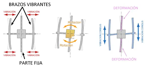
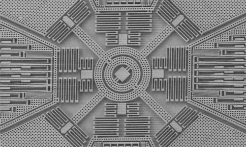
To register the effect of the Coriolis force, a MEMS has structures similar to those of an accelerometer. Certain parts of the body are subjected to vibration by resonance, and the effect of the Coriolis force deforms the structure (which can be measured by the variation in the system’s capacitance).
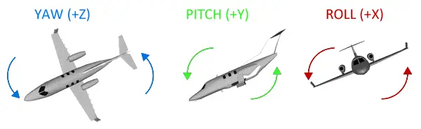
As with accelerometers, it is normal for the gyroscopes we use to be 3-axis, meaning they independently register rotation in X, Y, and Z, which allows determining the magnitude and direction of the rotation.
One consequence of using the Coriolis force is that vibratory gyroscopes, unlike other types of gyroscopes, do not register the angle turned but the angular velocity (which is the rate of change of the angle with respect to time).
The units in the International System are rad/s (equivalently s-1), although other units such as º/s, rev/s (rps), or rev/min (rpm) are frequently used.
To obtain the position angle of the sensor, it is necessary to integrate with respect to time (something usually done by the sensor’s internal electronics)-.
We never tire of repeating that integral measurements are never a good idea because they involve the accumulation of measurement errors and noise, which causes drift in the measurement.
Indeed, the biggest problem we find with vibration gyroscopes is that in the medium and long term they have drift (meaning the measurement progressively deviates from the real value, even with the sensor static).
On the other hand, gyroscopes are sensors with fast response and high precision in short time periods. Furthermore, they respond well to sudden changes and are relatively immune to noise, always within short time ranges.
If you have read the post about the accelerometer, you will see that its measurement characteristics are opposite to those of gyroscopes, so (attention SPOILER) they complement each other very well.
We will see this in depth in the next post, how to measure inclination with IMU, Arduino, and complementary filter, where we will finally combine both devices to make a sensor more robust than either one independently.