What is a TCA9548A?
The TCA9548A is an 8-channel I2C extender, which we can use with a microprocessor like Arduino.
The function of an I2C extender is to connect multiple buses to a single bus. It could be understood as a particular type of multiplexer, but specially designed for I2C communication.
In this way, the TCA9548A has an I2C bus input, with two lines (SDA and SCL). On the other hand, it has 8 I2C bus outputs, each with its corresponding two lines (SDA and SCL).
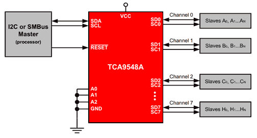
During its operation, the I2C extender connects the input bus to one (or none) of the outputs, allowing the processor to communicate with multiple buses.
Probably the most frequent use we can make of an I2C extender is to allow us to connect multiple devices with the same address, and that do not allow us to change it.
It can also be useful for communicating I2C buses with different voltages, without the need to use a level shifter. This makes it possible to communicate buses at voltages of 1.8V, 2.5V, 3.3V, and 5V.
Communication with the TCA9548A itself is done through the input bus, so it is very simple to control it from a processor.
The operating voltage of the TCA9548A is 1.65V to 5.5V, and it operates with I2C buses with a frequency of 0 up to 400KHz.
Price
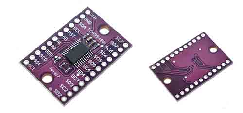
TCA9548A devices are very cheap. We can find them for about €0.45 from international sellers on eBay and AliExpress.
How does a TCA9548A work?
In summary, internally the TCA9548A can be considered as a matrix of 16 switches, which connect the SDA and SCL lines of the input bus, with the SDA and SCL lines of the 8 outputs.
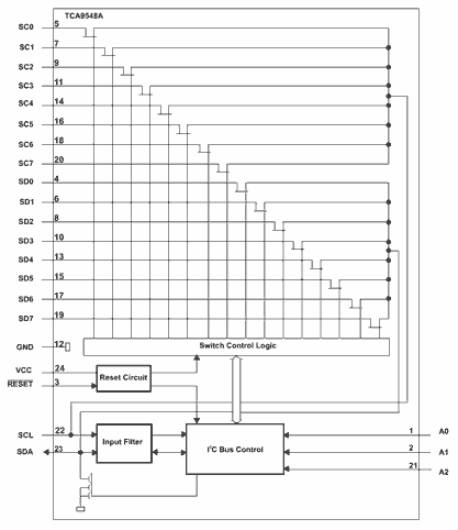
The TCA9548A’s electronics receive the input I2C bus signal and configure the switch matrix. In this way, it connects the input I2C bus to one of the outputs.
The default address of the TCA9548A is 0x70, but it can be varied from 0x70 to 0x77 using the A0, A1, and A2 pins, according to the following table.
| A2 | A1 | A0 | Adreess |
|---|---|---|---|
| L | L | L | 0x70 |
| L | L | H | 0x71 |
| L | H | L | 0x72 |
| L | H | H | 0x73 |
| H | L | L | 0x74 |
| H | L | H | 0x75 |
| H | H | L | 0x76 |
| H | H | H | 0x77 |
Assembly diagram
The connection of TCA9548A is quite simple. On one hand, we power the module to the input bus voltage (in the example, GND and 5V), and the SDA and SCL of the input I2C bus.
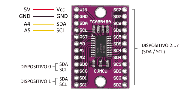
On the other hand, we connect the outputs that we need, up to a maximum of 8, each with its SDA and SCL lines.
The connection, seen from Arduino, would be as follows.
The address of the TCA9548A itself can be set between 0x70 and 0x77 with the A0, A1, and A2 pins, according to the table we saw before.
The TCA9548A can be reset by setting RST to LOW. By default, it is pull-up, so you can leave it unconnected if you do not need it in the project.
Finally, keep in mind that, depending on how the devices you connect are and the length of the cables, you may need to add Pull-UP resistors for the input or output I2C buses.
Code examples
I2C Scanner
The first thing we are going to do is to detect the TCA9548A itself, for which we are going to run an I2CScanner.
Since we have not yet taken any action on the TCA9548A, the input and outputs are disconnected, so the only address we should detect is that of the TCA9548A itself, at the configured address (0x70-0x77)
#include "Wire.h"

void scanI2CBus(byte from_addr, byte to_addr, void(*callback)(byte address, byte result) )
{
  byte rc;
  byte data = 0;
  for( byte addr = from_addr; addr <= to_addr; addr++ ) {
    rc = twi_writeTo(addr, &data, 0, 1, 0);
    callback( addr, rc );
  }
}

void scanFunc( byte addr, byte result ) {
  Serial.print("addr: ");
  Serial.print(addr,DEC);
  Serial.print( (result==0) ? " Encontrado!":"       ");
  Serial.print( (addr%4) ? "\t":"\n");
}

const byte start_address = 8;
const byte end_address = 119;

void setup()
{
    Wire.begin();

    Serial.begin(9600);
    Serial.print("Escaneando bus I2C...");
    scanI2CBus( start_address, end_address, scanFunc );
    Serial.println("\nTerminado");
}

void loop()
{
    delay(1000);
}I2C Scanner for TCA9548A
Once we have verified that the extender is detected correctly, we can act to detect the devices connected on the output buses.
There are libraries for manipulating the TCA9548A, but selecting a channel is very simple, we just have to write a byte with the channel we want to connect to.
Therefore, we will normally avoid using a library, and simply have a function like the following void tcaselect(uint8_t i), to handle the TCA9548A.
In this way, we can modify the normal I2C scanner to detect the devices on the different outputs.
/**
 * TCA9548 I2CScanner.ino -- I2C bus scanner for Arduino
 *
 * Based on https://playground.arduino.cc/Main/I2cScanner/
 *
 */

#include "Wire.h"


#define TCAADDR 0x70

void tcaselect(uint8_t i) {
  if (i > 7) return;

  Wire.beginTransmission(TCAADDR);
  Wire.write(1 << i);
  Wire.endTransmission();
}

void setup()
{
    while (!Serial);
    delay(1000);

    Wire.begin();

    Serial.begin(115200);
    Serial.println("\nTCA escaner listo");

    for (uint8_t t=0; t<8; t++) {
      tcaselect(t);
      Serial.print("  Escaneando salida "); Serial.println(t);

      for (uint8_t addr = 0; addr<=127; addr++) {
        if (addr == TCAADDR) continue;

        Wire.beginTransmission(addr);
        if (!Wire.endTransmission()) {
          Serial.print("  - Encontrado I2C 0x");  Serial.println(addr,HEX);
        }
      }
    }
    Serial.println("Finalizado");
}

void loop()
{
}Download the code
All the code in this post is available for download on Github.

