
What is a magnetic reed?
A magnetic reed is an electromechanical device that behaves as a switch that is activated in the presence of a magnet.
Magnetic reed sensors are widely used. For example, many door and window alarms work by placing a magnet on the element and detecting the opening with a magnetic reed. We can also place the magnet on a door or display case to turn on a light, etc.
Since a magnetic reed is still a switch, we can use this device to turn a device on or off directly. Of course, we can also use Arduino’s digital inputs to read the state of the magnetic reed, similar to what we saw in the post reading a button with Arduino.
Magnetic switches have the advantage of being inexpensive, simple, and do not require power to operate. Additionally, they work with both AC and DC.
However, being electromechanical devices, the switching time is relatively high, on the order of 1-5 ms. If our application has a higher switching speed (for example, to make a tachometer), we should use a Hall sensor, as we saw in this post.
Additionally, magnetic reeds have a limited lifespan, meaning there is a number of switches they can make before becoming damaged. However, in some devices, it can be up to 100 million switches, which is sufficient for most applications. Finally, the presence of vibrations or sudden movements can alter their operation and lead to incorrect measurements.
Price
Magnetic reed switches are very inexpensive devices. We can find magnetic reeds from €0.10 on international sellers on Ebay or AliExpress.
The price depends on the maximum intensity and voltage, the maximum power they can handle, and the switching speed and lifespan.

How does a magnetic reed work?
Physically, a magnetic reed consists of two ferromagnetic nickel elements located inside a sealed glass bulb.
When a magnetic field is close, the generated force causes both elements to make contact, closing the electrical circuit.

There are also magnetic reeds whose state is normally closed and open the electrical circuit in the presence of a magnetic field. We can even find magnetic reeds that have both outputs, one normally open and one normally closed, in the same device.
The magnetic field required to activate the switch is typically in the range of 50 Gauss.
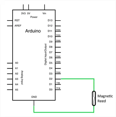
Electrical schematic
The electrical schematic is simple. We will use Arduino’s internal pull-up resistors, so we simply connect the magnetic reed between GND and the digital input we want to use.
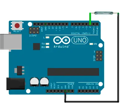
Assembly schematic
The assembly on a breadboard would be as follows.
Code examples
The following code shows a simple example. We use a digital input, with the internal pull-up resistor, to read the state of the magnetic reed. If the sensor is activated, the input will read LOW, and in that case, we turn on the LED integrated on the board. Of course, in a real project, instead of turning on the integrated LED, we would execute the actions we wanted.
const int pinSensor = 2;
const int pinLED = 13;

void setup() {
  //configure pin as input with internal pull-up resistor
  pinMode(pinSensor, INPUT_PULLUP);
  pinMode(pinLED, OUTPUT);
}

void loop() {
  int value = digitalRead(pinSensor);

  if (value == LOW) {
    digitalWrite(pinLED, HIGH);
  } else {
    digitalWrite(pinLED, LOW);
  }

  delay(1000);
}
Of course, in a real project, instead of turning on the integrated LED, we would execute the actions we wanted.
Download the code
All the code in this post is available for download on Github. 
