What is an optointerrupter?
An optointerrupter is a sensor shaped like a “U” that allows detecting an object that passes through the device by the inner slot.
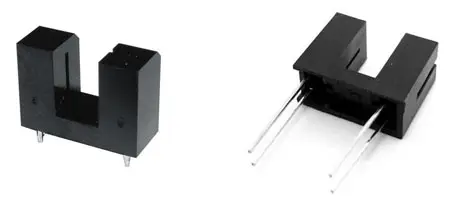
Optointerrupters are simple sensors. One end contains an infrared emitting diode, while the other contains a phototransistor that receives the signal. When an object passes through the slot, it interrupts the infrared light beam, which is detected by the phototransistor.
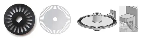
Optointerrupters are widely used as encoders to detect the speed and position of a motor shaft. To do this, a disk with slots coupled to the shaft is used. It is also possible to use a transparent sheet on which black stripes are printed, something that is frequently found in printers.
In addition to being used as an encoder, an optointerrupter can be used to detect any type of object that interrupts the beam, for example, to detect the closing of a door, or as an optical limit switch in the movement of a machine.
Another widely used sensor for making encoders and tachometers is a Hall sensor, as we saw in the post Detecting Magnetic Fields with Arduino and A3144 Hall Sensor
Price
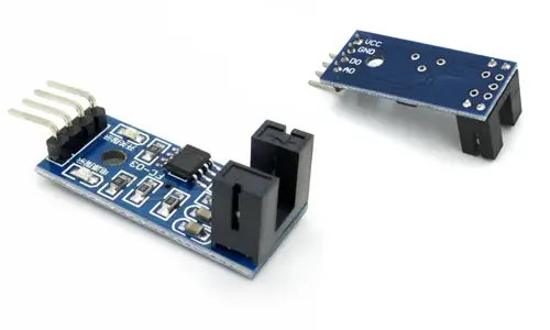
We can find boards with optoacouplers for around 0.60€ from international sellers on eBay and AliExpress.
They are not easy to find components because each seller gives them a different name and the translations on these pages are quite bad. Try searching for “photo interrupter” or “arduino speed sensor” or “arduino slotted sensor”.
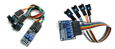
We can also find optointerrupters in 2 or 4-channel setups. In general, they are usually more expensive than buying them individually and there is no advantage to having them in the same device, so they are generally not recommended.
As it is a simple sensor, we can also assemble it ourselves. In general, it is not worth it since only the components would cost us more, not to mention the time needed and the quality we could obtain, so it is normal to use a commercial model.
Assembling our own sensor only makes sense when, due to the location where the sensor has to be mounted, we do not have space to house a commercial board and we are forced to integrate the component.
Electrical schematic
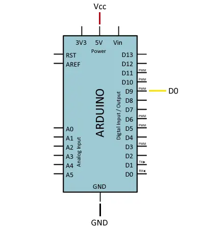
If you use a commercial board, which as we said is generally recommended, the assembly of an optointerrupter to Arduino is really simple. We power the module through Vcc and GND by connecting them, respectively, to the 5V and GND outputs on Arduino.
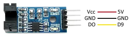
On the other hand, we connect the digital output of the sensor to a digital input to read the state of the sensor.
If you decide to do the entire assembly yourselves, the electrical schematic is not complicated either. We simply need to power the module correctly, respecting the component’s schematic. As you can see, the power direction of both branches is usually inverted. Consult the datasheet of your optocoupler to verify its pinout.
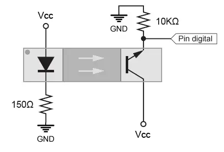
We power the photodiode through a resistor to limit its current, as we saw in Turning on a LED with Arduino. In the phototransistor branch, we use a pull-down resistor to read the state of the sensor, as we saw in Reading a button with Arduino.
Code examples
We have several options for reading an optointerrupter with Arduino. If we are detecting the presence of an object, we simply read the state of the digital input, as we saw in the post Digital Inputs on Arduino.
When the sensor is triggered, we perform the necessary actions, such as incrementing a counter, or measuring the time between triggers.
const int sensorPin = 9;

void setup() {
  Serial.begin(9600);   //start serial port
  pinMode(sensorPin , INPUT);  //define pin as input
}

void loop(){
  int value = 0;
  value = digitalRead(sensorPin );  //digital pin read

  if (value == LOW) {
      Serial.println("Optointerrupter activated");
  }
  delay(1000);
}However, in the case of using the optointerrupter as an encoder, we usually use Arduino interrupts, which will considerably simplify our code. The downside is that we will have to debounce the inputs and that Arduino UNO and Nano only have two external interrupts, which in some cases may not be enough.
For more information, see the post What are and how to use interrupts in Arduino and Reading a button with interrupts in Arduino
Download the code
All the code from this post is available for download on Github.

