What is a digipot?
A digital potentiometer (or digipot) is a device capable of varying its resistance from a digital signal provided by a processor such as Arduino.
The technical name is a digital-to-analog resistive converter (RDAC), although it is frequently referred to as a digital potentiometer because it exhibits behavior similar to a conventional potentiometer, but with electronic control.
Typically, a digipot is internally constituted by multiple resistances forming stages, the activation of which is controlled by transistors. The number of stages or levels activated is controlled by a digital signal and determines the total resistance presented by the device.
Although its name may suggest it, digipots should not be considered a direct replacement for a potentiometer. The main limitation is the maximum current that can pass through the device, which is typically in the range of a few milliamperes.
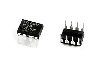
Devices in the MCP41XXX family are 8-bit digital potentiometers (256 levels), available in resistances of 10 kO (MCP41010), 50 kO (MCP41050), and 100 kO (MCP41100).
The MCP41XXX is controlled by SPI, so it is easy to read. The supply voltage is 2.7V to 5.5V. The maximum current that can pass through the device is 5mA.
Due to the limitations of maximum current that a digital potentiometer can provide, these are rarely used directly in circuits. Instead, they are usually used to control amplification stages through transistors or operational amplifiers.
Potentiometers are useful in measurement instrument control projects, fine adjustment of controllers, regulation of amplifiers, interface with especially sensitive sensors, among others.
Price
We can find digipots like those in the MCP41XXX series for about €0.60 by searching international sellers on eBay or AliExpress.
Assembly diagram
The connection of a digipot MCP41XXX is simple, we simply power the integrated circuit from Arduino using GND and 5V and connect the data pins as we saw in the entry on the SPI bus.
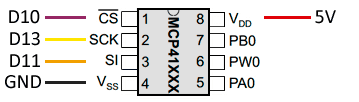
While the connection seen from the Arduino side would be like this.
The SPI pins shown are valid for the Arduino Uno, Nano, and Mini Pro models. For other Arduino models, consult the pinout scheme corresponding.
Code examples
The following example shows the use of a digipot MCP41XXX. First, we set the digipot to maximum, intermediate, and minimum resistance values. Finally, we create a continuous loop varying the resistance between maximum and minimum.
//SCK > D13
//SI  > D11
//CS  > D10

#include <SPI.h>
const byte address = 0x11;
const int CS = 10;

int digitalPotWrite(int value)
{
  digitalWrite(CS, LOW);
  SPI.transfer(address);
  SPI.transfer(value);
  digitalWrite(CS, HIGH);
}

void setup()
{
  pinMode(CS, OUTPUT);
  SPI.begin();

  // Maximum resistance
  digitalPotWrite(0);
  delay(5000);

  // Intermediate resistance
  digitalPotWrite(126);
  delay(5000);

  // Minimum resistance
  digitalPotWrite(255);
  delay(5000);
}

void loop()
{
  for (int i = 0; i <= 255; i++)
  {
    digitalPotWrite(i);
    delay(100);
  }
  delay(2000);
  for (int i = 255; i >= 0; i--)
  {
    digitalPotWrite(i);
    delay(100);
  }
  delay(2000);
}
Download the code
All the code from this post is available for download on Github. 
