What is a flowmeter?
A flowmeter is a sensor that allows us to measure the amount of water that passes through a pipe. We can connect a flowmeter to a processor like Arduino to obtain the sensor’s measurement.
The name of the flowmeter comes from the term flow rate, which is the relationship between volume and time. The units in the international system are m^3/s, with other common units being l/s and l/min. The flow rate depends on various factors, mainly the pipe section and the supply pressure.
In domestic installations, the usual pipe diameters are 1” (DN25), 3/4” (DN20) and 1/2” (DN15), with the latter being the standard for faucets. The pressure should be in the range of 100 kPA (1 Kg/cm2) to 500kPA (5 Kg/cm2).
Usual flow rates for 1/2” pipe installations (standard for faucets) are 0.1 l/s (6 l/min) and 0.2 l/s (12 l/min). For 3/4” pipes, we can have flow rates around 20 l/min, and for 1” pipes, around 35 l/min.
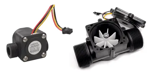
Within the field of flowmeters that we can use in our home electronic and home automation projects, we have various models such as the YF-S201, FS300A, FS400A. Each one has different characteristics, although the selection criterion between these three will be the pipe diameter.
We can use a flowmeter in our projects, for example, to determine the consumption of an installation, regulate the flow by acting on a pump, control the filling of a tank, or control an irrigation system.
Price
We can find the YF-S201 (1/2” connection) for 2.50€, the FS300A (3/4” connection) for 4.50€, and the FS400A (1” connection) for 6.50€, searching from international sellers on eBay or AliExpress.
How does a flowmeter work?
Flowmeters like the YF-S201, FS300A, and FS400A are made up of a sealed plastic housing and a rotor with blades inside. As the fluid passes through the sensor, the flow causes the rotor to spin.
The speed of rotation is determined by a magnet fixed to the rotor, which is detected by a hall sensor external to the housing. Therefore, no electrical part is in contact with the fluid.
The sensor output is a square wave whose frequency is proportional to the flow rate.
The conversion factor K between frequency (Hz) and flow rate (L/min) depends on the constructive parameters of the sensor. The manufacturer provides a reference value in its Datasheet. However, the constant K depends on each flowmeter. With the reference value, we can have an accuracy of +-10%. If we want higher accuracy, we must carry out a test to calibrate the flowmeter.
| Model | Connection | Flow Rates | K |
|---|---|---|---|
| YF-S201 | 1/2” | 1-30 L/min | 7.5 |
| FS300A | 3/4” | 1-60 L/min | 5.5 |
| FS400A | 1” | 1-60 L/min | 3.5 |
Assembly diagram
The connection of the flowmeter is very simple. On one hand, we power the sensor by connecting Vcc and Gnd, respectively, to 5V and Gnd on Arduino. On the other hand, we connect the sensor output SIG to a digital pin that allows using interrupts.
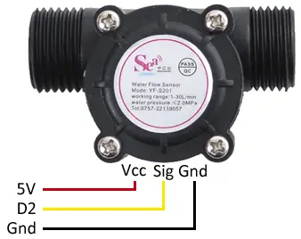
While the connection, seen from Arduino, would be as follows.
Code examples
Calculate the flow rate
To read the flowmeter, we must calculate the frequency of the sensor’s output signal. To do this, we will use an interrupt that counts pulses in a certain interval, and by dividing the number of pulses by the interval in seconds, we will obtain the frequency.
Next, we convert the frequency measurement to flow rate, for which we use the factor K, which as we have said depends on the flowmeter model we are using.
const int sensorPin = 2;
const int measureInterval = 2500;
volatile int pulseConter;

// YF-S201
const float factorK = 7.5;

// FS300A
//const float factorK = 5.5;

// FS400A
//const float factorK = 3.5;

void ISRCountPulse()
{
  pulseConter++;
}

float GetFrequency()
{
  pulseConter = 0;

  interrupts();
  delay(measureInterval);
  noInterrupts();

  return (float)pulseConter * 1000 / measureInterval;
}

void setup()
{
  Serial.begin(9600);
  attachInterrupt(digitalPinToInterrupt(sensorPin), ISRCountPulse, RISING);
}

void loop()
{
  // obtain frequency in Hz
  float frequency = GetFrequency();

  // calculate flow rate L/min
  float flow_Lmin = frequency / factorK;

  Serial.print("Frequency: ");
  Serial.print(frequency, 0);
  Serial.print(" (Hz)\tFlow rate: ");
  Serial.print(flow_Lmin, 3);
  Serial.println(" (L/min)");
}
Calculate the consumption
If we want to calculate the volume of water consumed, we simply need to integrate with respect to time.
const int sensorPin = 2;
const int measureInterval = 2500;
volatile int pulseConter;

// YF-S201
const float factorK = 7.5;

// FS300A
//const float factorK = 5.5;

// FS400A
//const float factorK = 3.5;

float volume = 0;
long t0 = 0;

void ISRCountPulse()
{
  pulseConter++;
}

float GetFrequency()
{
  pulseConter = 0;

  interrupts();
  delay(measureInterval);
  noInterrupts();

  return (float)pulseConter * 1000 / measureInterval;
}

void SumVolume(float dV)
{
  volume += dV / 60 * (millis() - t0) / 1000.0;
  t0 = millis();
}

void setup()
{
  Serial.begin(9600);
  attachInterrupt(digitalPinToInterrupt(sensorPin), ISRCountPulse, RISING);
  t0 = millis();
}

void loop()
{
  // obtain frequency in Hz
  float frequency = GetFrequency();

  // calculate flow rate L/min
  float flow_Lmin = frequency / factorK;
  SumVolume(flow_Lmin);

  Serial.print(" Flow rate: ");
  Serial.print(flow_Lmin, 3);
  Serial.print(" (L/min)\tConsumption:");
  Serial.print(volume, 1);
  Serial.println(" (L)");
}
Download the code
All the code in this post is available for download on Github. 
