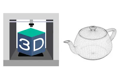
We are delving into the 3D design and printing section, and we are properly starting with the 3D design tutorials by looking at the foundation, the fundamental ways to represent a 3D object on a computer.
After a few posts dedicated to the Anycubic 3D printer, and having seen an overview of the 3D printing process in the previous post, it’s time to dive deep into the exciting world of 3D.
I’ll tell you in advance, if you are one of those eager to “melt plastic,” you probably won’t find this post so interesting (nor do you need it!). But you don’t want to be “just another one” of those who turn on the printer, open FreeCAD, or download an STL, and start printing without further ado.
You want to become 3D experts and understand the intricacies of this exciting world. And for that, the best thing is to have a good foundation, which will allow you to understand what you are doing, speak properly, and also avoid unnecessary “loops” and steps when working with 3D objects.
And it all starts by understanding how that thing we call a “3D object” (and it’s still a “strange entity”) is represented on a computer. Understanding the differences will be important when we tackle the 3D design or printing process.
So in this post, we will see the main ways to represent a 3D object on a computer.
Point Cloud
The most basic way to represent a 3D object is a point cloud, where each point is a vertex with X, Y, Z coordinates. Optionally, they can have other characteristics like color.
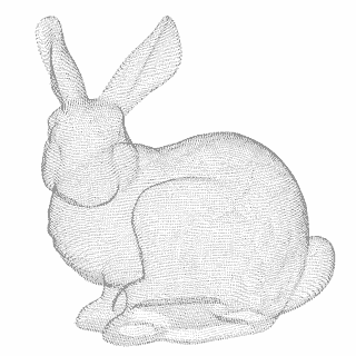
Point clouds are important in the world of 3D printing, mainly because 3D scanners return a point cloud.
Due to a simple physical limitation, any sensor (a camera, a probe) must take a finite number of points. Therefore, regardless of the 3D scanner you have, the result of a scan will always be a point cloud.
To convert a point cloud into a 3D mesh or a 3D solid, we will need two additional processes called triangulation and reverse engineering, respectively, which we will briefly see in the next post.
Meshed Models
This is the most common way to represent a 3D model and the one we are probably most accustomed to. They are widely used in animation for video games or movies.
A 3D mesh consists of a series of points, connected by edges, which in turn form faces. The faces have normals (the direction the face “points” to).
Generally, meshes can have a material, or texture, that is, some kind of color representation. Often, the material is an image (bitmap) that is “projected” onto the mesh. The relationship between the flat image and its correspondence on the faces is known as UVW mapping.
Within the representation using 3D meshes, we are going to highlight the following types:
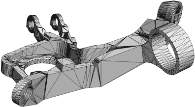
Triangulated Meshes
A triangulated mesh, as its name suggests, is simply a mesh made entirely of triangles. It is the most “basic” mesh we can conceive, as each face can be contained by three sides/three vertices at a minimum.
Internally, and with rare exceptions, your computer only knows how to represent triangulated surfaces. So, even when we are using any of the other forms of representation, when it comes to displaying it on the screen, it internally converts it into a triangulated mesh.
Your graphics card contains circuits specially designed to accelerate calculations of triangle and light ray intersections, and between them (collisions).
Polygonal Meshes (Quads, Ngons)
A polygonal mesh is a mesh formed by polygons with N sides (sometimes called Ngons) and is, in a way, an evolution of triangulated surfaces.

Polygonal meshes are generally simpler and more comfortable to manipulate by the designer, hiding edges that are not really relevant. They are also more comfortable to texture and animate.
On the other hand, Quads are polygons with 4 sides. A 100% quad mesh is a mesh formed entirely by 4-sided polygons, and they have certain advantages for modeling, especially for doing Sub-D (which we will see in the next section).
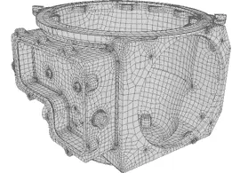
However, even if we handle polygons with N sides, the mesh is internally made of triangles. The program simply “hides” some of the edges and provides us with tools to make it more comfortable to use.
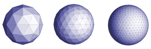
Subdivision Meshes (Sub-D)
Subdivision modeling (sometimes abbreviated Sub-D) is a mesh-based modeling technique that, currently, we could consider one of the main 3D drawing methods.
Sub-D modeling consists of a mesh, generally polygonal, to which a subdivision algorithm has been applied.
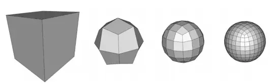
The subdivision algorithm adds additional intermediate points and, according to some criterion (which depends on the algorithm), moves the position of the vertices to give “smoothness” to the mesh. The process can be repeated several times, obtaining different levels of increasing detail.
The designer can modify the vertices of the different subdivision levels at any time to modify the mesh. This way it is possible to achieve both smooth shapes and great detail at the same time without having to move a large number of vertices.
There are different subdivision algorithms, among which we can highlight the traditional Loop, the ubiquitous Catmull Clark, or the more modern OpenSubDiv developed by Pixar.
With Sub-D modeling, meshes with a large number of polygons are obtained and, therefore, heavy and slow to process. Normally, subsequently, the high-resolution model is “projected” onto a low-resolution model, and part of the detail becomes part of the “normal map.”
Sub-D modeling has great advantages both from a design point of view and for texture application and mesh animation, which is why it is one of the main 3D drawing models.
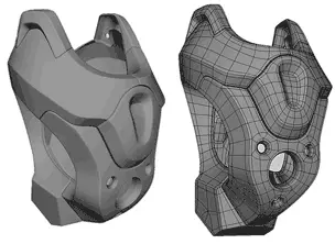
Finally, Sub-D modeling is suitable for modeling complex geometric shapes and models that require many curves, such as organic modeling. On the other hand, it is not as suitable for models with flat faces or sharp edges.
Surface Modeling
Surface modeling is a radically different way from meshes for representing three-dimensional objects, based on mathematical models. These mathematical models allow describing a curved surface in three-dimensional space.
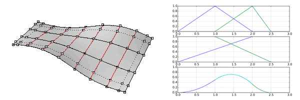
Generally, NURBS surfaces (Non Uniform Rational B-Splines) are used, or some of their variations such as T-Splines or T-NURCCs (Non-Uniform Rational Catmull-Clark Surfaces with T-junctions).
By using a mathematical model, surfaces represent a continuous medium instead of a discrete approximation. Thus, the representation of a cylinder has a circle as its base and top, instead of a polygon with a certain number of sides. Therefore, they provide great detail and smoothness in curves.
Typical surface modeling tools are extrusion, revolution, lofting, and rail sweeping. Additionally, holes can be defined in the surface and curves can be projected onto surfaces.
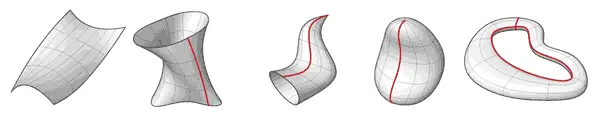
Surfaces, by definition, have no volume. Therefore, they are not physically fabricable/realizable. To be able to manufacture them, a thickening operation will need to be applied or they will need to be closed into a solid.
With notable exceptions, in general, surfaces also cannot be represented by the graphics card. To do so, they are internally converted into a triangular mesh.
Surface modeling is traditionally linked to the design of manufacturing parts with complex curves (plastic parts, automotive, etc.). It allows representing curved models with ease, as well as flat faces or edges. However, it is not suitable for models with irregular curves, such as organic modeling.
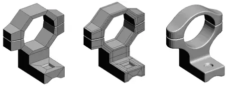
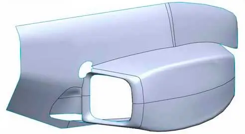
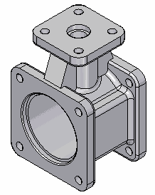
Solid Modeling
Solid modeling is the traditional way of operation of what we know as CAD software. Solid modeling is, roughly speaking, made up of surface modeling along with the concept of “inside” and “outside.”
For example, when performing an additive extrusion operation (protrusion) or a subtractive extrusion operation (hollowing, hole), the system performs the necessary intersections and normal changes to correctly represent the system.
Much of the complexity of solid modeling systems lies in the ways to efficiently calculate these operations (such as K-trees), especially as the complexity of the part increases.
Being, in reality, based on surface modeling, the basic tools remain the same (extrusion, revolution, lofting, sweeping…). But CAD software incorporates many more operations and tools that allow them to be performed more intuitively and, generally, more similar to physical machining operations (chamfer, fillet, hole, rib).
As we said, solid modeling is traditionally linked with CAD software, and it is suitable for representing mechanical parts and fabricable objects.
It is interesting to consider that the relationship occurs in both directions. Solid modeling represents the objects we manufacture well, partly because we use it to manufacture them.
As CAD evolves, so does the complexity of the parts we manufacture.
These are, in a very summarized way, the ways we have to represent a 3D object on a computer. Each one with its advantages and disadvantages, and more suitable for one type of object than for others.
In case you were wondering, in general, it is not easy to switch from one to another. Something we will see in the next post about triangulation, retopology, and reverse engineering.
In the upcoming posts, we will see 3D design software and CAD software that use one or several of these methods for 3D design. Meanwhile, if you liked the topic and want to add something, or if you have any questions, you can leave us a comment!