Interrupts are a very powerful and valuable mechanism in processors and automata. Arduino, of course, is no exception. In this post, we will see what interrupts are and how to use them in our code.
To understand the usefulness and necessity of interrupts, let’s assume that we have Arduino connected to a sensor (for example, an optical encoder that counts motor revolutions, a detector that emits a water level alarm in a tank, or a simple stop button).
If we want to detect a state change in this input, the method we have used so far is to use digital inputs to repeatedly query the value of the input, with a time interval (delay) between queries.
This mechanism is called “polling” and has 3 clear disadvantages:
- It assumes continuous processor and energy consumption, as it has to constantly ask for the state of the input.
- If the action needs to be attended to immediately (for example, in a collision alert) waiting until the point in the program where the query is made may be unacceptable.
- If the pulse is very short, or if the processor is busy doing another task while it occurs, it is possible that we miss the trigger and never see it.
To solve this type of problem, microprocessors incorporate the concept of an interrupt, which is a mechanism that allows associating a function with the occurrence of a specific event. This associated callback function is called ISR (Interruption Service Routine).
When the event occurs, the processor “exits” immediately from the normal program flow and executes the associated ISR function, completely ignoring any other task (that’s why it’s called an interrupt). After finishing the associated ISR function, the processor returns to the main flow, at the same point where it was interrupted.
As we can see, interrupts are a very powerful and convenient mechanism that improves our programs and allows us to perform actions that would not be possible without using interrupts.
To use interrupts with physical devices (such as buttons, optical sensors, … ) we must first eliminate the “bounce” effect, as you can see in the post Applying Debounce When Using Interrupts in Arduino
Interrupts in Arduino
Arduino has two types of events in which to define interrupts. On one hand, we have timer interrupts (which we will see when we talk about timers). On the other hand, we have hardware interrupts, which respond to events occurring on certain physical pins.
Within hardware interrupts, which are the focus of this post, Arduino is capable of detecting the following events.
RISING, occurs on the rising edge fromLOWtoHIGHFALLING, occurs on the falling edge fromHIGHtoLOWCHANGING, occurs when the pin changes state (rising + falling)LOW, executes continuously while in theLOWstate
The pins capable of generating interrupts vary depending on the Arduino model.
In Arduino Uno and Nano, there are two interrupts, 0 and 1, associated with digital pins 2 and 3. The Arduino Mega has 6 interrupts, on pins 2, 3, 21, 20, 19, and 18 respectively. The Arduino Due has interrupts on all its pins.
| Model | INT0 | INT1 | INT2 | INT3 | INT4 | INT5 |
|---|---|---|---|---|---|---|
| UNO | 2 | 3 | ||||
| Nano | 2 | 3 | ||||
| Mini Pro | 2 | 3 | ||||
| Mega | 2 | 3 | 21 | 20 | 19 | 18 |
| Leonardo | 3 | 2 | 0 | 1 | 7 | |
| Due | On all pins | |||||
The ISR Function
The function associated with an interrupt is called ISR (Interruption Service Routine) and, by definition, must be a function that takes no arguments and returns nothing.
Two ISRs cannot execute simultaneously. If another interrupt is triggered while an ISR is executing, the ISR functions are executed one after the other.
Effects of the Interrupt and Time Measurement
Interrupts have effects on Arduino’s time measurement, both outside and inside the ISR, because Arduino uses Timer-type interrupts to update time measurement.
During the execution of an interrupt, Arduino does not update the value of the millis and micros functions. That is, the execution time of the ISR is not counted and Arduino has an offset in time measurement.
If a program has many interrupts and they take a long execution time, Arduino’s time measurement can become very distorted compared to reality (again, a reason to keep ISRs short).
Inside the ISR, other interrupts are disabled. This means:
- The millis function does not update its value, so we cannot use it to measure time inside the ISR. (we can use it to measure time between two different ISRs)
- As a consequence, the delay() function does not work, as its operation is based on the millis() function
- The micros() function updates its value inside an ISR, but starts to give inaccurate time measurements after the 500us range.
- Consequently, the delayMicroseconds function works in that time range, although we should avoid its use because we should not introduce waits inside an ISR.
Creating Interrupts in Arduino
To define an interrupt in Arduino we use the function:
attachInterrupt(interrupt, ISR, mode);
Where interrupt is the number of the interrupt we are defining, ISR is the associated callback function, and mode is one of the available options (FALLING, RISING, CHANGE, and LOW)
However, it is cleaner to use the digitalPinToInterrupt() function, which converts a Pin to its equivalent interrupt. This facilitates changing the board model without having to modify the code.
attachInterrupt(digitalPinToInterrupt(pin), ISR, mode);
Other interesting functions for interrupt management are:
DetachInterrupt(interrupt), cancels the interrupt.NoInterrupts(), disables the execution of interrupts until further notice (equivalent to cli())Interrupts(), re-enables interrupts (equivalent to sei())
Testing Interrupts in Arduino
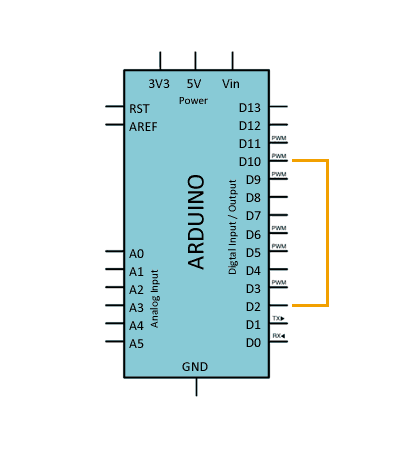
To test interrupts in Arduino, we are going to use a digital output from Arduino to emulate a digital signal.
In the real world, it would be another device (a sensor, another processor…) that would generate this signal, and we would capture it with Arduino.
We connect pin digital 10 to pin digital 2, associated with interrupt 0, using a cable.
Blinking an LED Through Interrupts
In the following code, we define digital pin 10 as an output, to emulate a square wave with a period of 300ms (150ms ON and 150ms OFF).
To visualize the operation of the interrupt, on each active edge of the simulated pulse, we turn on/off the integrated LED on the board, so the LED blinks at intervals of 600ms (300ms ON and 300ms OFF)
By now, seeing an LED blink might not seem very spectacular, but it’s not as simple as it seems. We are not turning the LED on with a digital output, but rather it is the triggered interrupt that turns the LED on and off (the digital pin only emulates an external signal).
const int emuPin = 10;

const int LEDPin = 13;
const int intPin = 2;
volatile int state = `LOW`; // define as volatile

void setup() {
  pinMode(emuPin, OUTPUT);
  pinMode(LEDPin, OUTPUT);
  pinMode(intPin, INPUT_PULLUP);
  attachInterrupt(digitalPinToInterrupt(intPin), blink, CHANGE);
}

void loop() {
  //this part is to emulate the output
  digitalWrite(emuPin, HIGH);
  delay(150);
  digitalWrite(emuPin, LOW);
  delay(150);
}

void blink() {
  state = !state; // change the state to make it blink
  digitalWrite(LEDPin, state);
}
Counting Interrupt Triggers
In the following code, we use the same digital pin to emulate a square wave, this time with a 2-second interval (1s ON and 1s OFF).
In each interrupt, we update the value of a counter. Later, in the main loop, we check the counter value, and if it has been modified, we display the new value.
When running the code, we will see consecutive numbers printed in the serial monitor at two-second intervals.
const int emuPin = 10;

const int intPin = 2;
volatile int ISRCounter = 0;
int counter = 0;

void setup()
{
  pinMode(emuPin, OUTPUT);

  pinMode(intPin, INPUT_PULLUP);
  Serial.begin(9600);
  attachInterrupt(digitalPinToInterrupt(intPin), interruptCount, FALLING);
}

void loop()
{
  //this part is to emulate the output
  digitalWrite(emuPin, HIGH);
  delay(1000);
  digitalWrite(emuPin, LOW);
  delay(1000);

  if (counter != ISRCounter)
  {
    counter = ISRCounter;
    Serial.println(counter);
  }
}

void interruptCount()
{
  ISRCounter++;
}
Of course, our goal is to use hardware interrupts not only with other digital devices, but also with physical devices such as buttons, optical sensors…
However, as we have mentioned, these devices generate a lot of noise during state changes, causing interrupts to be triggered multiple times. This phenomenon is called “bounce” and we will learn how to eliminate it in the next post.
Download the Code
All the code from this post is available for download on Github. 
