What is the NRF24L01?
The NRF24L01 is a wireless communication chip manufactured by Nordic Semiconductor that we can connect to a processor such as Arduino
The NRF24L01 integrates an RF transceiver (transmitter + receiver) at a frequency between 2.4GHz to 2.5GHz, a free band for free use. The transmission speed is configurable between 250 Kbps, 1Mbps, and 2 Mbps and allows simultaneous connection with up to 6 devices.
The NRF24L01 also incorporates the logic necessary for robust communication, such as error correction and data forwarding if necessary, freeing the processor from this task. The module is controlled through the SPI bus, making it easy to control it from a processor like Arduino.
The frequency band is from 2400 to 2525 MHz, being able to choose between 125 channels spaced at a rate of 1MHz. It is recommended to use frequencies from 2501 to 2525 MHz to avoid interference with Wifi networks.
The supply voltage of the NRF24L01 is 1.9 to 3.6V, although the data pins are tolerant to 5V. The Stand By power consumption is low, and about 15mA during transmission and reception. Logically, the module’s consumption is higher, reaching up to 150-250 mA in models with more powerful antennas.
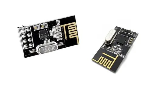
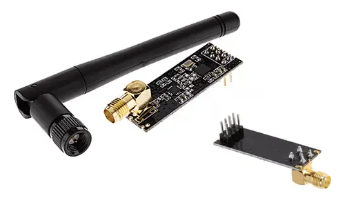
There are two versions of modules that mount the NRF24L01, one with an integrated zig-zag antenna and a maximum range of 20-30 meters, and the high-power version that incorporates an amplifier and an external antenna, with a maximum range of 700-1000 meters.
However, the real range is limited by many factors, even under conditions of direct visibility without obstacles. With the module of integrated antenna and powered from Arduino and a transmission speed of 2 Mbps, the range will be hardly 2-3 meters.
A factor of great impact on the range is the power supply of the module. To achieve the maximum range, it is advisable to power the module with an external source of 3.3V, stable and with enough power.
The NRF24L01 modules are widely used for their low price and good characteristics. We can use them, for example, for remote reception of sensors such as temperature pressure, home automation and smart buildings applications, remote activation of devices such as lighting, alarms, and control or monitoring of robots in the range of up to 700 meters.
Price
Currently, the 2.4 GHz RF modules that mount the NRF24L01 are very cheap devices. We can find the model with an integrated zig-zag antenna for 0.65€, looking at international sellers on eBay or AliExpress.
The version with an amplifier and an external antenna has a higher price of 1.70€, but in return, they improve the range up to 700-1000 meters, although to achieve this range we will need to power the module with an external source of 3.3V.
Logically, in both cases, we will need two NRF24L01 modules, one as a transmitter and the other as a receiver.
Assembly Scheme
The connection of a 2.4 GHz RF NRF24L01 module is simple, we simply power the integrated chip from Arduino using GND and 5V and connect the data pins as we saw in the entry about the SPI bus.
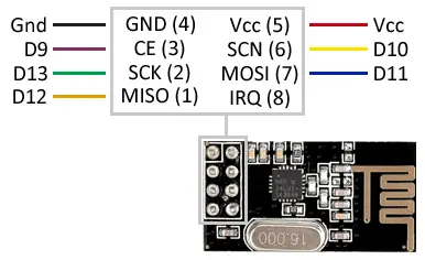
While the connection seen from the Arduino side would be like this.
As we said, the module’s operation improves if we use an external 3.3V source. In this case, remember to put Gnd in common. For optimal operation, it is also convenient to connect a 100pF - 1uF capacitor between Gnd and 3.3V of the NRF24L01.
The module operates at 3.3V. Do not power it at 5V or you will damage the module.
The SPI pins listed are valid for Arduino Uno, Nano, and Mini Pro models. For other Arduino models, consult the pinout scheme accordingly.
Code Examples
To control the NRF24L01, we will use the RF24 library, available at this link.
The library provides code examples, which is advisable to review. The following examples are modifications based on those available in the library.
Send a string
The following example shows the sending of a text string from a transmitting Arduino to a receiving Arduino, which upon receiving the text displays it by the serial port.
Transmitter code
#include <nRF24L01.h>
#include <RF24.h>
#include <RF24_config.h>
#include <SPI.h>

const int pinCE = 9;
const int pinCSN = 10;
RF24 radio(pinCE, pinCSN);

// Single radio pipe address for the 2 nodes to communicate.
const uint64_t pipe = 0xE8E8F0F0E1LL;

char data[16]="Hello world" ;

void setup(void)
{
  radio.begin();
  radio.openWritingPipe(pipe);
}

void loop(void)
{
  radio.write(data, sizeof data);
  delay(1000);
}
Receiver code
#include <nRF24L01.h>
#include <RF24.h>
#include <RF24_config.h>
#include <SPI.h>

const int pinCE = 9;
const int pinCSN = 10;
RF24 radio(pinCE, pinCSN);

// Single radio pipe address for the 2 nodes to communicate.
const uint64_t pipe = 0xE8E8F0F0E1LL;

char data[16];

void setup(void)
{
  Serial.begin(9600);
  radio.begin();
  radio.openReadingPipe(1,pipe);
  radio.startListening();
}

void loop(void)
{
  if (radio.available())
  {
    radio.read(data, sizeof data);
    Serial.println(data);
  }
}
Send integer or float variables
The following example shows the sending of integer or float variables from a transmitting Arduino to another receiver, which displays the data via the serial port. The transmitting Arduino sends two arbitrary data, in the example millis()/1000 as an integer and 3.14 as a float.
The receiver receives the data and, depending on the identifier, converts the received data to integer or float, and displays the result via the serial port.
Transmitter code
#include <SPI.h>
#include <nRF24L01.h>
#include <RF24.h>

const int pinCE = 9;
const int pinCSN = 10;
RF24 radio(pinCE, pinCSN);

// Single radio pipe address for the 2 nodes to communicate.
const uint64_t pipe = 0xE8E8F0F0E1LL;

float data[2];

void setup()
{
  radio.begin();
  radio.openWritingPipe(pipe);
}

void loop()
{
  data[0]= 3.14;
  data[1] = millis()/1000.0;

  radio.write(data, sizeof data);
  delay(1000);
}
Receiver code
#include <SPI.h>
#include <nRF24L01.h>
#include <RF24.h>

const int pinCE = 9;
const int pinCSN = 10;
RF24 radio(pinCE, pinCSN);

// Single radio pipe address for the 2 nodes to communicate.
const uint64_t pipe = 0xE8E8F0F0E1LL;

float data[3];

void setup()
{
  radio.begin();
  Serial.begin(9600);
  radio.openReadingPipe(1, pipe);
  radio.startListening();
}

void loop()
{
  if (radio.available())
  {
    radio.read(data, sizeof data);
    Serial.print("Data0= " );
    Serial.print(data[0]);
    Serial.print("Data1= " );
    Serial.print(data[1]);
    Serial.println("");
  }
  delay(1000);
}
